

Spiral driving device and mop using same
A screw drive and mop technology, applied in the field of mops, can solve the problems of one-way bearing losing transmission function, stuck and wearing one-way bearing, etc.
- Summary
- Abstract
- Description
- Claims
- Application Information
AI Technical Summary
Problems solved by technology
Method used
Image

Examples
Embodiment Construction
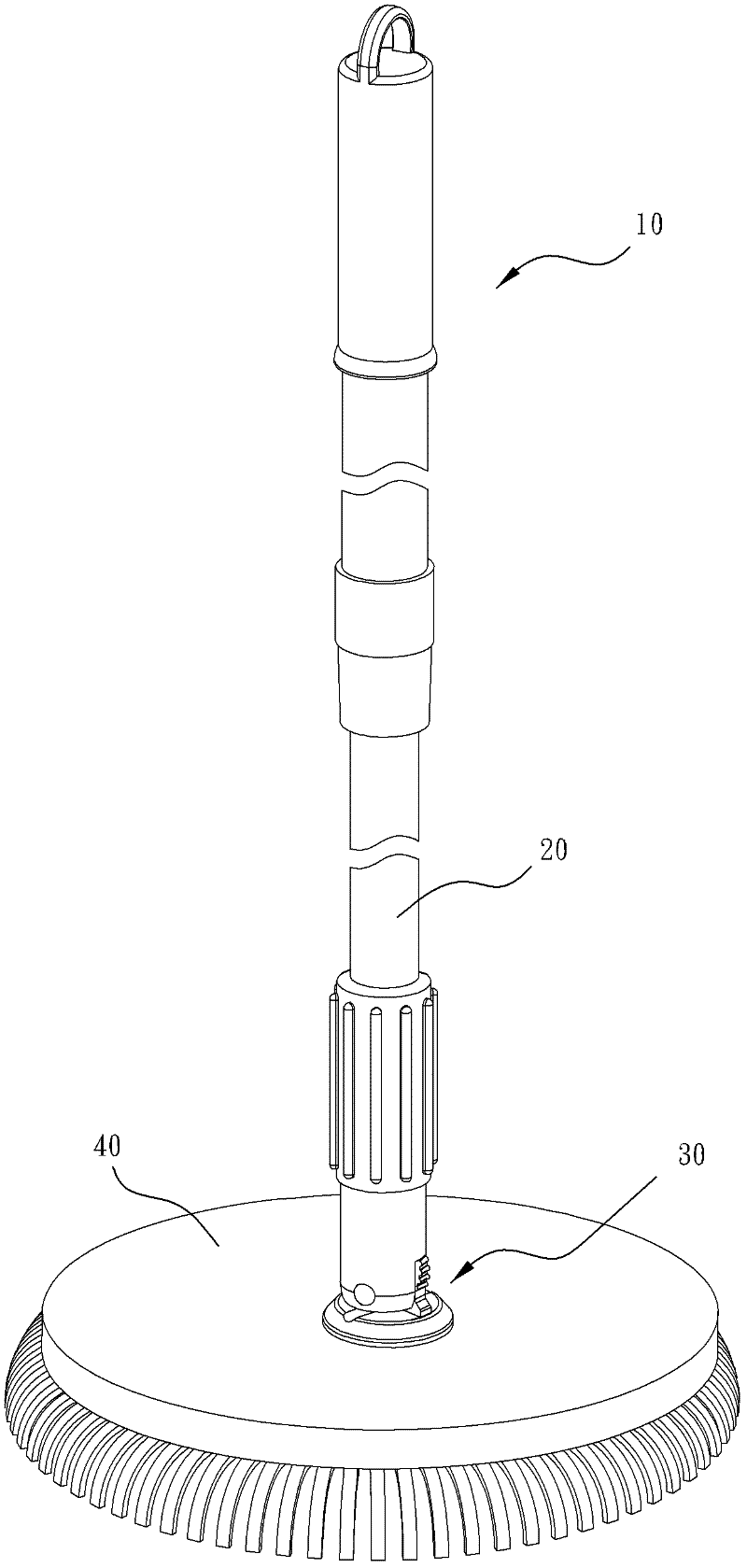
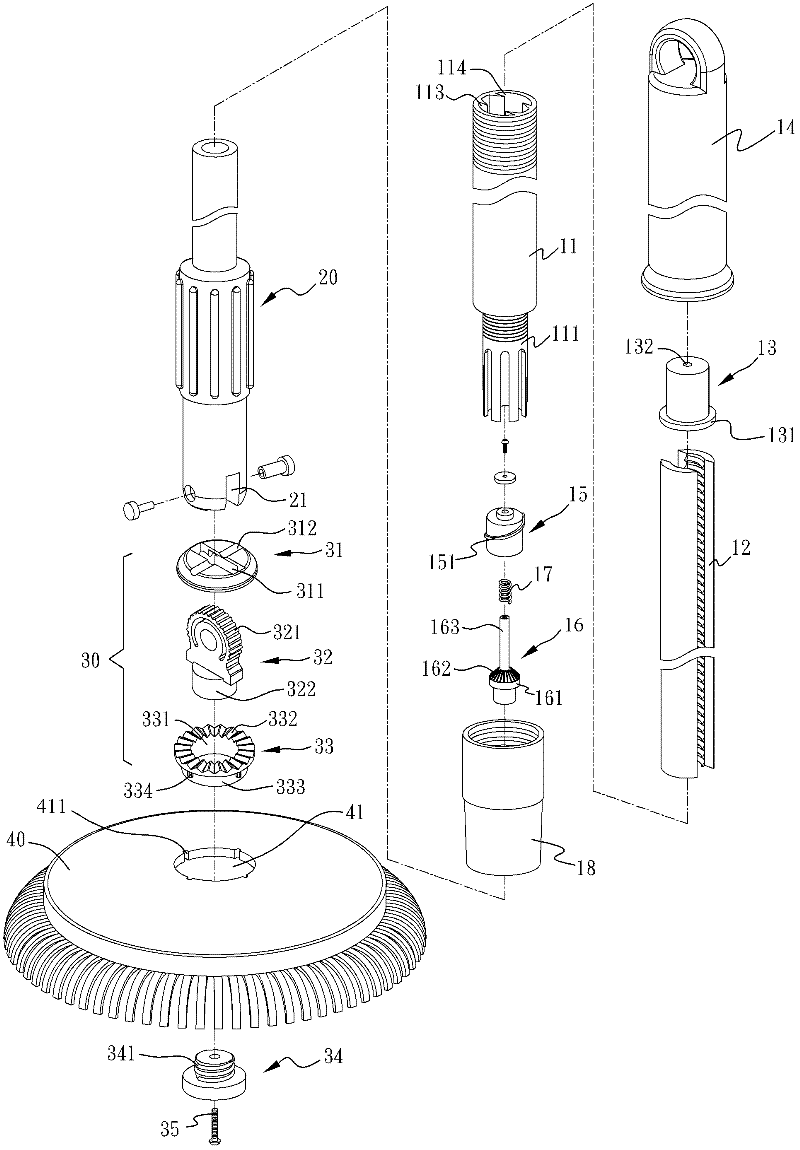
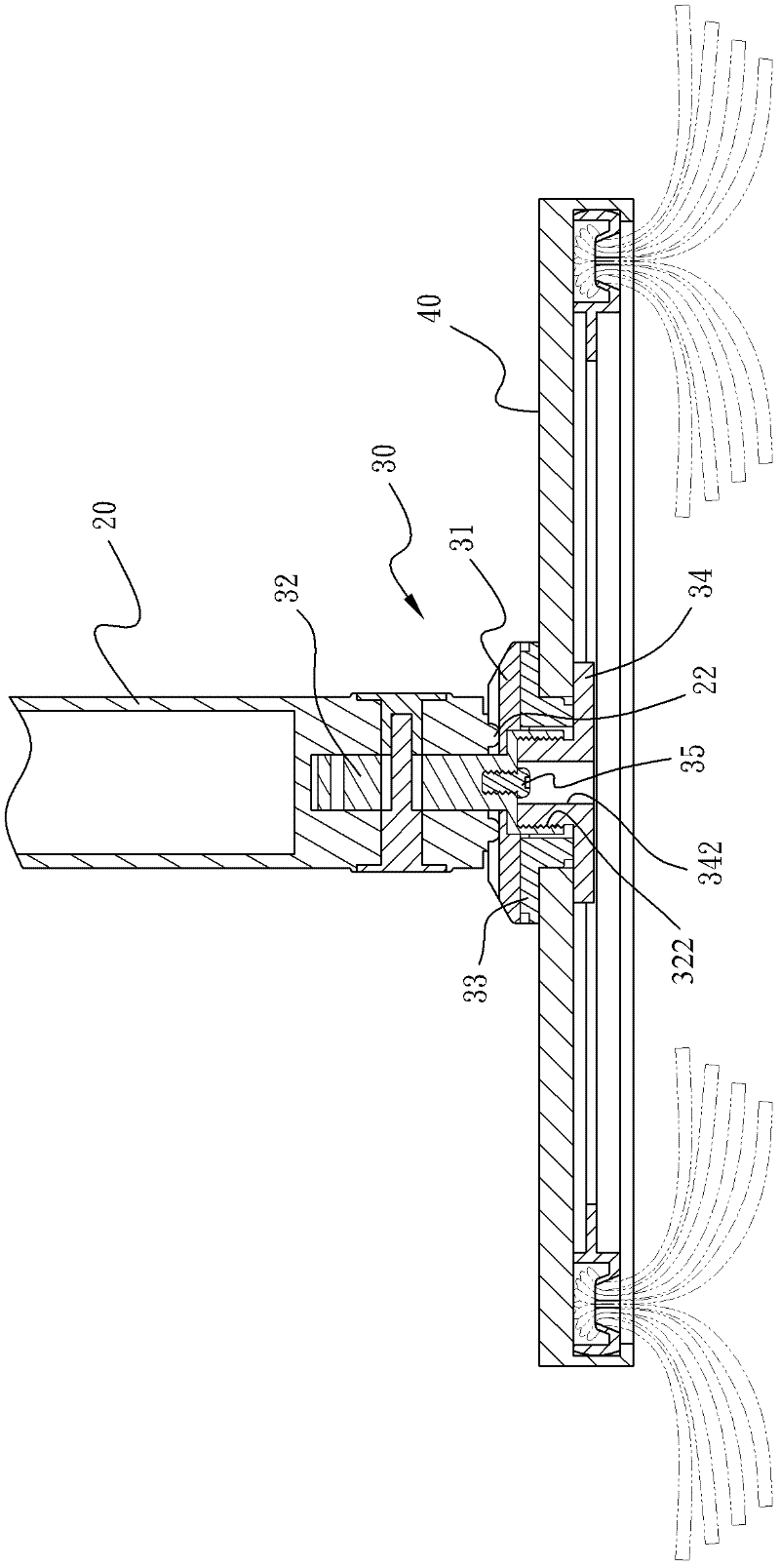
[0062] refer to Figure 1 to Figure 4 , in the first embodiment of the mop of the present invention, it mainly includes a columnar screw driving device 10, a connecting rod 20 that is coaxially connected to the screw driving device 10 and driven by it, and a connecting device 30 that is installed The mop head 40 at the free end of the connecting rod 20 .
[0063] The screw driving device 10 includes an outer tube 11 . A bundle of tubes 111 extends coaxially from the bottom end of the outer tube 11 , and a ring-shaped shoulder 112 is formed at the junction of the bundle tube 111 and the outer tube 11 . Two pairs of convex ribs 113 are longitudinally formed on the inner wall of the outer tube 11, and a dovetail groove 114 is formed between each pair of convex ribs 113. There is a threaded tooth plate 12 , and the threads on the two tooth plates 12 form a continuous spiral correspondence, and are limited by the annular shoulder 112 . A sleeve 14 is coaxially locked on the top o...
PUM
 Abstract
Description
Claims
Application Information