
Decorative plate connecting bar and spliced decorative plate spliced by the decorative plate connecting bars

A technology of connecting strips and decorative panels, which is applied in the direction of floors, buildings, and building structures, and can solve problems such as structural defects of socket slots and socket tenons, easy damage to socket sockets and socket sockets, etc.

Inactive Publication Date: 2012-03-28
郑素梅
View PDF9 Cites 7 Cited by
  • Summary
  • Abstract
  • Description
  • Claims
  • Application Information

AI Technical Summary

Problems solved by technology

In order to solve this problem, a design of horizontal splicing or vertical splicing has appeared. The horizontal splicing decorative panel is shown in the Chinese patent with the patent number "200620004862.2" and the patent name "snap-in floor". However, due to the structural defects of the socket slots and tenons of the two decorative panel units, the socket slots and socket tenons of the two decorative panel units are still very easy to be damaged during the insertion process, so it is necessary to improve

Method used


Image

  • Decorative plate connecting bar and spliced decorative plate spliced by the decorative plate connecting bars
  • Decorative plate connecting bar and spliced decorative plate spliced by the decorative plate connecting bars
  • Decorative plate connecting bar and spliced decorative plate spliced by the decorative plate connecting bars

Examples


Embodiment 1

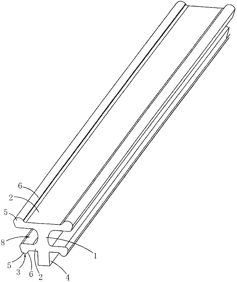
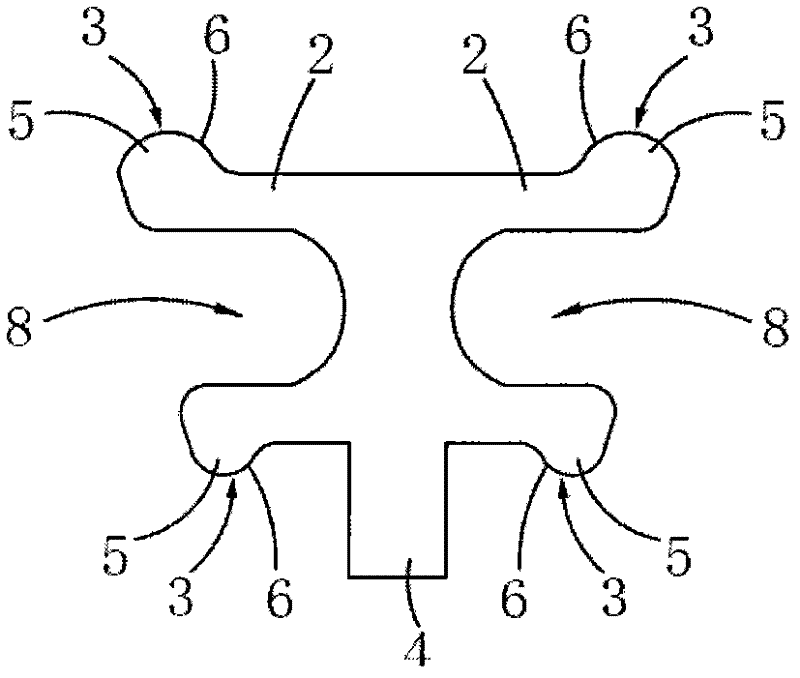
[0049] For the first embodiment of the decorative panel connecting strip of the present invention, see Figure 1 to Figure 2 As shown, it includes a connecting strip main body 1 in the shape of a straight strip, and two elastic connecting bodies 2 extend laterally on both sides of the connecting strip main body 1 respectively. A support body 4 extends from the bottom of the connecting bar main body 1 .

[0050] The connecting body 2 has a certain deformation ability, which is convenient for the clamping joint 3 to be clamped into the insertion slot of the decorative panel unit 10 , and can also fix the clamping joint 3 in the insertion slot of the decorative panel unit 10 .

[0051] When the decorative panel connecting strip is spliced ​​with the decorative panel unit 10, the two connecting bodies 2 extending transversely on the decorative panel connecting strip are inserted into the socket of the decorative panel unit 10 in the horizontal direction or close to the horizontal ...

Embodiment 2

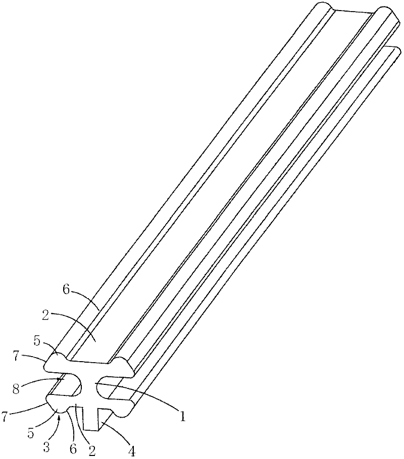
[0063] For the second embodiment of the decorative panel connecting strip of the present invention, see Figure 3 to Figure 4 As shown, the main structure, connection relationship and advantages of this embodiment are the same as those of Embodiment 1, and the similarities will not be repeated here. The length of the upper connecting body 2 is equal to the length of the lower connecting body 2 . The decorative panel connecting strip adopts a symmetrical design to increase its structural strength, and the decorative panel connecting strip is balanced in force to avoid the internal stress of the decorative panel connecting strip, so that the decorative panel connecting strip is not easy to be damaged and prolongs its service life.

[0064] The clip connector 3 includes a plug-in guide portion 7 , and a guide inclined surface is provided on the outer side of the plug-in guide portion 7 . It is more convenient and smooth when the decorative panel connecting strip and the decorati...

Embodiment 3

[0066] For the third embodiment of the decorative panel connecting strip of the present invention, see Figure 5 As shown, the main structure, connection relationship and advantages of this embodiment are the same as those of Embodiment 1, and the similarities will not be repeated here. Mark 9, the fracture mark 9 extends from the bottom of the connecting bar main body 1 to the top of the connecting bar main body 1, the height of the fracture mark 9 is less than the height of the connecting bar main body 1, and the connecting bar main body 1 forms a partial connection at the fracture mark 9. The decorative panel connecting strip can be broken at the fracture mark 9 without sawing off with a saw or the like.

[0067] In a preferred embodiment, the fracture mark 9 surrounds the main body 1 of the connecting strip, and the main body 1 of the connecting strip forms a partial connection at the fracture mark 9 .

[0068] The distance between two adjacent fracture marks 9 on the con...


PUM


Abstract

The invention discloses a decorative plate connecting bar, which comprises a connecting bar main body in shape of a straight bar, the two sides of the connecting bar main body are extended with two connecting bodies in the transverse direction toward the outside directions respectively, the outer ends of the two connecting bodies are formed with clamping heads respectively, and the bottom of the connecting bar main body is extended out with a support body. The decorative plate connecting bar is simple in structure, low in cost, balance in force during use, difficult to damage and long in service life, and the decorative plate connecting bar does not damage inserting slots of decorative plate unit; the spliced decorative plate is formed by splicing several decorative plate connecting bars and several decorative plate units, two adjacent decorative plate units are connected by one decorative plate connecting bar, the connecting bodies on the two sides of each decorative plate connecting bar are clamped in the inserting slots of two adjacent decorative plate units, the decorative plate connecting bars and the decorative plate units are firm in connection, both the decorative plate connecting bars and the decorative plate units are difficult to damage, the decorative plate connecting bars and the decorative plate units are difficult to separate, and the decorative plate connecting bars are easier and more convenient when the decorative plate units are spliced.

Description

technical field [0001] The invention relates to the technical field of a connecting strip and a spliced ​​decorative panel spliced ​​by several decorative panel units, in particular to a decorative panel connecting strip and a spliced ​​decorative panel spliced ​​using the decorative panel connecting strip. Background technique [0002] In the prior art, the decorative board is spliced ​​by a number of decorative board units, and the side of the decorative board unit is provided with a socket or tenon, and the decorative board unit is spliced ​​by the socket and the socket. One piece, however, since the slots and tenons are molded from the decorative panel unit, the decorative panel unit needs to be tilted at a set angle during the splicing process to make the slots and tenons of the two decorative panel units During the splicing process, it is necessary to change the insertion angle and / or the insertion direction once or twice. The splicing is more difficult, and in the spl...

Claims


Application Information

Patent Timeline
IPC IPC(8): E04F15/02
Inventor 戴东锡
Owner 郑素梅
Learn More