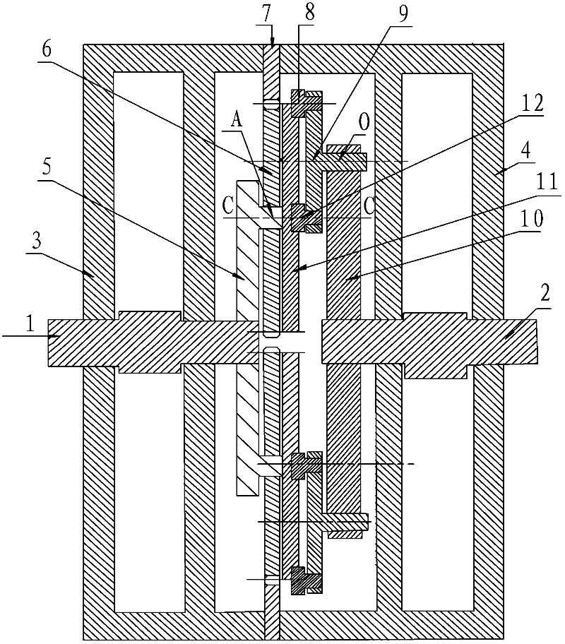
[0031] The invention discloses a planetary gear transmission device, which can increase the power of the output end under the premise of ensuring the synchronization of the input shaft and the output shaft.
[0032] The following will clearly and completely describe the technical solutions in the embodiments of the present invention with reference to the accompanying drawings in the embodiments of the present invention. Obviously, the described embodiments are only some, not all, embodiments of the present invention. Based on the embodiments of the present invention, all other embodiments obtained by persons of ordinary skill in the art without making creative efforts belong to the protection scope of the present invention.
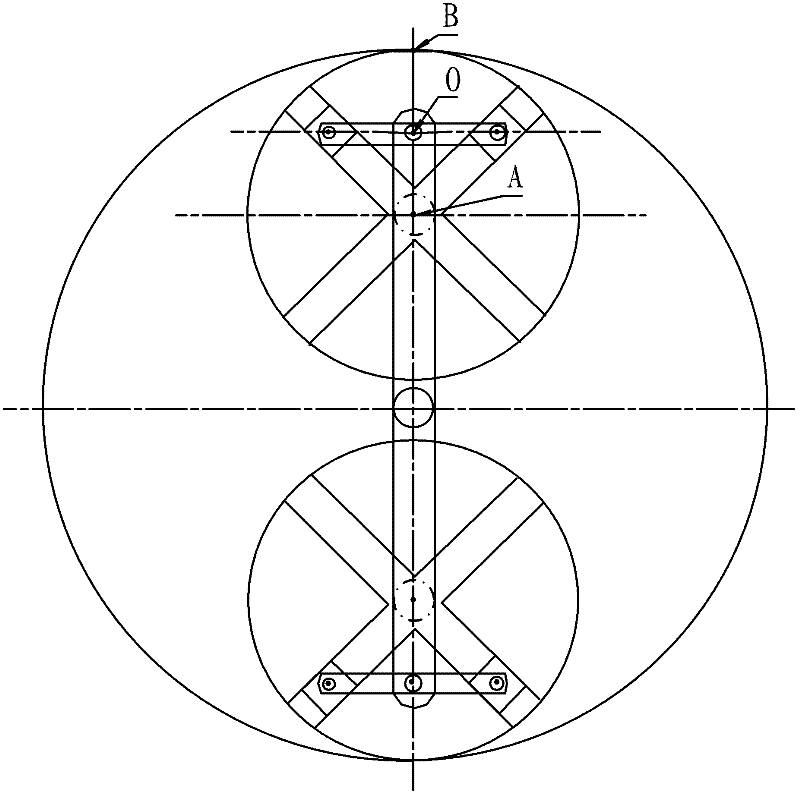
[0033] see figure 1 and figure 2 , figure 1 Schematic diagram of the cross-sectional structure of the front of the planetary gear transmission provided by the embodiment of the present invention; figure 2 It is a schematic diagram of the side structure of the planetary gear transmission provided by the embodiment of the present invention.
[0034] The planetary gear transmission provided by the embodiment of the present invention includes a casing 3, which is used to accommodate other internal structures and provide support and protection; the input shaft 1 and the output shaft 2 are rotatably installed inside the casing 3, such as figure 1 As shown, the input shaft 1 and the output shaft 2 are erected in the hole of the side wall inside the box body 3, and are connected by bearings. Both the input shaft 1 and the output shaft 2 have one end inside the box body 3, and the other end extends out of the box body 3 External, which facilitates the connection with other devices, and the axes of input shaft 1 and output shaft 2 are on the same straight line;
[0035] The core invention of the device is that it also includes:
[0036] Coaxially connected to the driving disc 5 at the end of the input shaft 1 inside the box body 3, the input shaft can drive the driving disc 5 to rotate synchronously, and the end surface of the driving disc 5 near the output shaft 2 is provided with a driving disc shaft near the edge A;
[0037] A planetary gear 6 rotatably connected to the driving disc shaft A;
[0038] The internal gear 7 arranged on the inner wall of the box body 3 and meshed with the planetary gear 6, the planetary gear 6 rotates and rotates under the action of the driving disc shaft A and the internal gear 7;
[0039] The sheave mechanism, the sheave mechanism includes a sheave 11 coaxially connected to the planetary gear 6, the sheave 11 and the planetary gear 6 rotate and rotate synchronously, the radius of the sheave 11 is the same as that of the planetary gear 6, and the sheave 11 is close to The end surface of the output shaft 2 side is provided with a cross chute, such as image 3 , Figure 4 As shown, the cross chute includes horizontal grooves and vertical grooves arranged perpendicularly to each other, and the horizontal grooves and vertical grooves respectively pass through the center of the end face and run through its surface; sliders 8, the specific number of sliders 8 are two, respectively with the cross The horizontal groove and the vertical groove of the chute are slidably matched, and the distance between the two is equal to the radius of the planetary gear 6; it also includes a grooved wheel 9, and the end face of the grooved wheel 9 near the input shaft 1 is provided with two for installation. The mounting holes of the slider 8, the distances from the two mounting holes to the center of the grooved wheel 9 are equal, and the center of the grooved wheel 9 near the end face of the output shaft 2 is provided with a grooved wheel axis O;
[0040] The driven disc 10 is rotatably connected to the sheave shaft O, and the entire chute mechanism rotates and rotates synchronously under the drive of the planetary gear 6, and the sheave shaft O on it drives the driven disc 10 to rotate, and the driven The disc 10 is coaxially connected to the end of the output shaft 2 inside the box body 3, thereby driving the output shaft 2 to rotate, and realizing the synchronization of the input shaft and the output shaft.
[0041]Compared with the structure in the prior art, the biggest improvement of the planetary gear transmission provided by the embodiment of the present invention is that the force point of resistance is always kept on the sheave by using the cooperation between the cross slide groove and the slider in the sheave structure. half of the radius of the planetary gear, and due to the connection between the planetary gear and the sheave, the planetary gear and the sheave rotate synchronously on the same axis, so the point of resistance force is at half of the radius of the planetary gear, that is to say, the driving disc shaft and the The meshing part of the planetary gear and the internal gear share the resistance of the force point of the resistance, which realizes the increase of the output power; and because the planetary gear and the internal gear are meshed, the planetary gear rotates and rotates under the driving force of the driving disc shaft, so The position of the meshing point changes synchronously with the rotation of the planetary gear, and the coaxial sheave structure also rotates synchronously, and then drives the rotation of the output shaft, so that the speed of the input shaft is equal to the speed of the output shaft, ensuring that the input shaft and output On the premise of shaft synchronization, the power at the output end is increased to meet the requirements of some special occasions. The planetary gear transmission device provided by the embodiment of the present invention can also be widely applied to various types of machinery, which reduces resource consumption and can achieve the purpose of energy saving and environmental protection.
[0042] The driving disc 5 is sleeved on the input shaft 1. In order to realize the synchronous rotation of the driving disc 5 driven by the input shaft 1, the two are connected by a key. keyway. This connection method is also detachable, which is very convenient. Of course, there are many ways to connect the input shaft 1 and the driving disc 5, such as keyless connection-profile connection, and only the most commonly used one is given here.
[0043] Similarly, the output shaft 2 and the driven disc 10 are also keyed.
[0044] We can connect the planetary gear 6 and the sheave 11 together through a variety of methods such as screw connection, key connection, spline connection, etc., so that the two can rotate and rotate synchronously. In this embodiment, the planetary gear 6 and the sheave 11 are specifically connected by bolts.
[0045] In order to optimize the above technical solutions, such as figure 1 As shown, the specific number of driving disc shafts A is two oppositely arranged, the planetary gears 6 are two respectively rotatably connected to the two driving disc shafts A, and the specific number of sheave mechanisms is two, which have One end of the sheave 11 is respectively connected to the two planetary gears 6 , and the sheave shaft (O) at the other end is respectively connected to the driven disc 10 . The cooperation between the two sets of planetary gears 6 and the sheave mechanism makes the whole transmission process more stable. Certainly, three sets, four sets or even more sets of planetary gears 6 and sheave mechanisms can also be provided as required.
[0046] Further, the two driving disc shafts A are arranged symmetrically with respect to the center of the driving disc 5 , and the two holes on the driven disc 10 respectively matched with the two grooved disc shafts O are arranged symmetrically about the center of the circle.
[0047] In order to realize synchronous rotation and rotation of the planetary gear 6 driven by the driving disc 5 , the driving disc 5 and the planetary gear 6 are connected by a shaft sleeve or a bearing.
[0048] Similarly, the sheave disc 9 and the driven disc 10 are connected by a shaft sleeve or a bearing.
[0049] In the present invention, through the combination of the internal gear 7, the planetary gear 6 and the sheave mechanism, the combination of the cross chute and the slide block on the sheave mechanism is cleverly used to form a new transmission mode. By driving one end of the planetary gear 6 or One end of the sheave mechanism enables the planetary gear 6 and the sheave mechanism to rotate and rotate along the internal gear 7 together, thereby meeting the requirements for use in some special occasions.
[0050] like Figure 5 As shown, the embodiment of the present invention also provides a power system, including a prime mover and a machine to be worked, the prime mover and the machine to be worked are connected through the above-mentioned planetary gear transmission, the prime mover is connected to one end of the input shaft, and the machine to be worked is connected Mechanically connected to one end of the output shaft, under the premise of ensuring the synchronization of input and output, the output power is 50% larger than the original input power, which can meet the requirements of some special occasions and reduce the consumption of resources. To achieve the purpose of energy saving and environmental protection.
[0051] Each embodiment in this specification is described in a progressive manner, each embodiment focuses on the difference from other embodiments, and the same and similar parts of each embodiment can be referred to each other.
[0052] The above description of the disclosed embodiments is provided to enable any person skilled in the art to make or use the invention. Various modifications to these embodiments will be readily apparent to those skilled in the art, and the general principles defined herein may be implemented in other embodiments without departing from the spirit or scope of the invention. Therefore, the present invention will not be limited to the embodiments shown herein, but is to be accorded the widest scope consistent with the principles and novel features disclosed herein.