Dynamic calculating method of wind-caused vibration and windage yaw of contact net of electrified railway

An electrified railway, wind-induced vibration technology, applied in measuring devices, instruments, surveying and mapping, and navigation, etc., can solve the problems of lack of catenary wind-induced vibration, lack of research on wind deflection of conductors, etc., to achieve a wide range of applications, strong controllability, calculation Efficient effect

Inactive Publication Date: 2012-03-28
CHINA RAILWAY FIRST SURVEY & DESIGN INST GRP
View PDF0 Cites 19 Cited by
  • Summary
  • Abstract
  • Description
  • Claims
  • Application Information

AI Technical Summary

Problems solved by technology

At present, the dynamic calculation method of catenary wind-induced vibration and wind deflection is not yet mature in the world, and there is still a lack of calculation method for catenary wind-induced vibration in China, and the wind deflection value of the thread is approximately determined by the static calculation method according to the given uniform wind speed. The dynamic calculation method of the wind deflection of the conductor under the action of wind pressure has not yet been studied

Method used


Image

  • Dynamic calculating method of wind-caused vibration and windage yaw of contact net of electrified railway
  • Dynamic calculating method of wind-caused vibration and windage yaw of contact net of electrified railway
  • Dynamic calculating method of wind-caused vibration and windage yaw of contact net of electrified railway

Examples


Embodiment Construction

[0027] The present invention will be described in detail below in combination with specific embodiments.

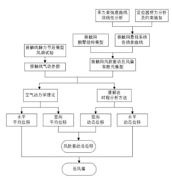
[0028] see figure 1 The flow shown is for the dynamic calculation of the wind-induced vibration displacement value and wind deviation value of the electrified railway catenary. The specific steps are as follows:

[0029] Step 1: Test the aerodynamic parameters of the contact line.

[0030] Through the static section model wind tunnel test of the contact line, the aerodynamic parameters of the contact line are tested to determine the wind load characteristics at different wind speeds; the aerodynamic parameters of the contact line are the three-component force coefficients of the contact line.

[0031] Since the cross-sectional shape of the contact wire is a circle with suspension grooves and alloy type identification grooves, which is not an ordinary regular circular shape, it is necessary to test the aerodynamic force of the contact wire through the static section model...


PUM


Abstract

The invention relates to a dynamic calculating method of wind-caused vibration and windage yaw of a contact net of an electrified railway. With the development of a high-speed railway, an influence degree on security of train operation by wind becomes more obvious; and effects of strong wind at a wind field and a wind gap as well as an effect of wind caused by train operation will enable large and complex vibration and windage yaw to occur at a contact net, so that a dynamic quality of high speed operation of a bow net will be influenced and bow net contact security will be threatened. The method comprises the following steps that: a wind tunnel test of a contact wire static force segment model is utilized to test an aerodynamic force parameter of a contact wire; a finite element model of wind-caused vibration and windage yaw of a contact net is established; average displacement of a contact net thread is calculated; and a spectral representation method is employed to simulate a turbulent flow wind speed time history and a time history analysis method is employed to calculate dynamic displacement of the contact net thread; and vertical average displacement and vertical dynamic displacement are superposed to obtain total displacement of wind-caused vibration of the contact net thread; and horizontal average displacement and horizontal average displacement are superposed to obtain total windage yaw of the contact net thread. According to the invention, a method is provided for dynamic calculation of wind-caused vibration and windage yaw of a contact net; and moreover, the method is suitable for application to power transmission line route.

Description

technical field [0001] The invention belongs to the technical field of railway electrification, and in particular relates to a dynamic calculation method for wind-induced vibration and wind deflection of an electrified railway catenary. Background technique [0002] With the development of high-speed railways, especially in unfavorable environmental conditions such as wind zones, tuyere or train wind effects, the safety of train operation is increasingly affected by strong winds. According to the operating conditions of electrified railways at home and abroad, especially high-speed railways, pantograph-catenary accidents caused by wind are increasing year by year. Due to the strong wind effect of the wind area and the tuyere, the vortex wind field effect at the tunnel entrance, or the wind effect of the train when passing up and down in the tunnel, the catenary will have greater and more complex vibration and wind deflection, which not only affects the pantograph-catenary hi...

Claims


Application Information

Patent Timeline
Patent Type & Authority Applications(China)
IPC IPC(8): G01B21/02G01C1/00
Inventor 田志军廖海黎刘改红赵玮韩佳栋王玉环马存明吴家岚李晋宫衍圣孙永革宋杰张学武田升平
Owner CHINA RAILWAY FIRST SURVEY & DESIGN INST GRP
Why Eureka
Try Eureka