Slot array antenna and radar device

An array antenna and slit technology, applied in the field of radar devices, can solve problems such as the reduction of sidelobe suppression effects

Active Publication Date: 2012-03-28
FURUNO ELECTRIC CO LTD
View PDF11 Cites 5 Cited by
  • Summary
  • Abstract
  • Description
  • Claims
  • Application Information

AI Technical Summary

Problems solved by technology

[0009] However, even with the slot array antenna 100 disclosed in Patent Document 1, for example, when it is used as an antenna for a ship radar, the angle in the vertical direction of the antenna (as defined by the z-axis in the y-z plane) may vary due to ship motion. Angle) changes, so sometimes the suppression effect of the side lobe is reduced

Method used


Image

  • Slot array antenna and radar device
  • Slot array antenna and radar device
  • Slot array antenna and radar device

Examples


no. 1 Embodiment approach

[0049] (1) overall composition

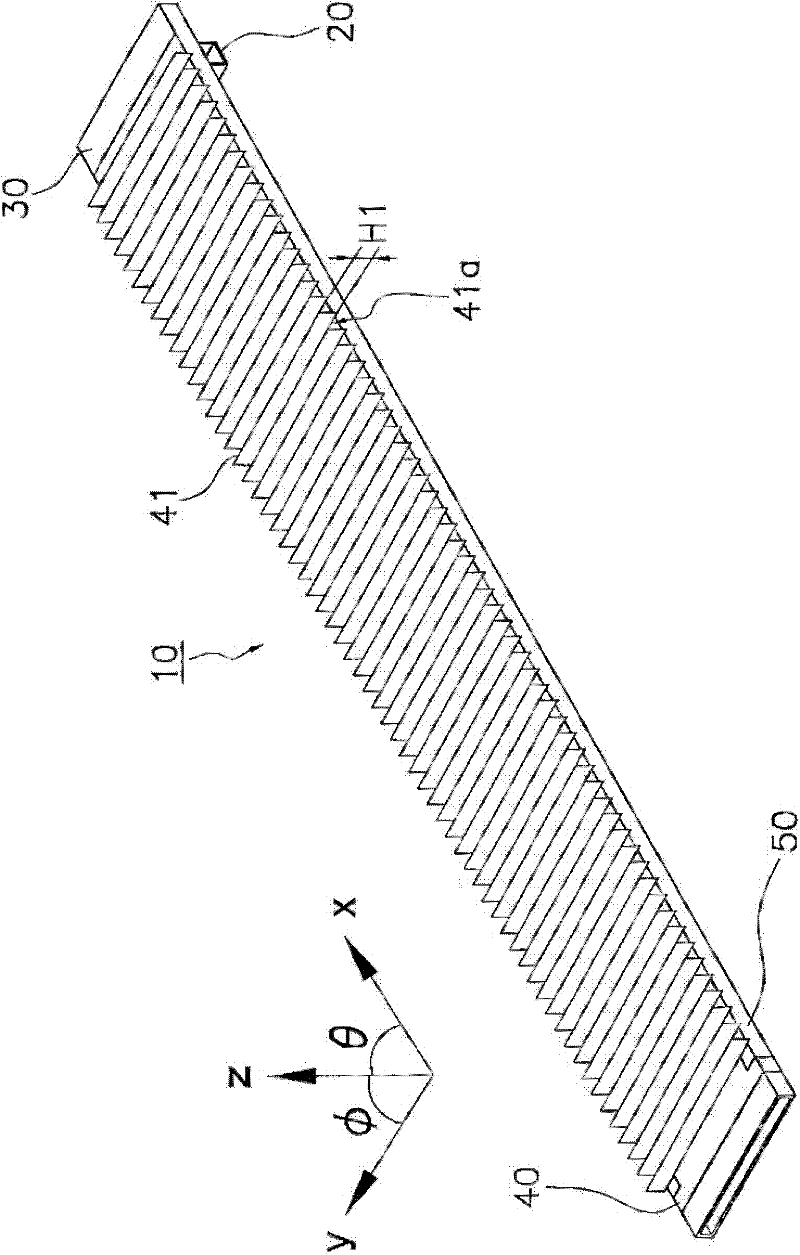
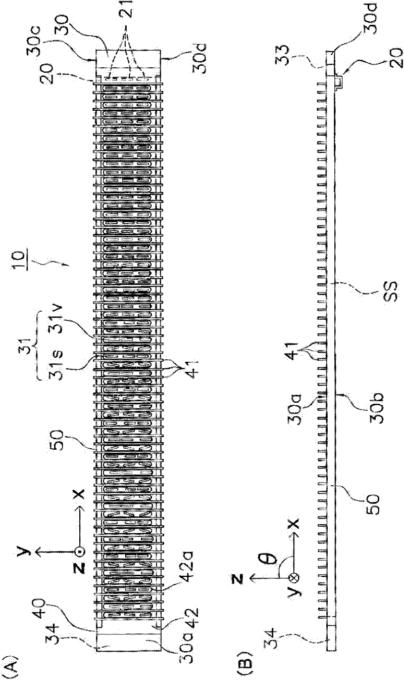
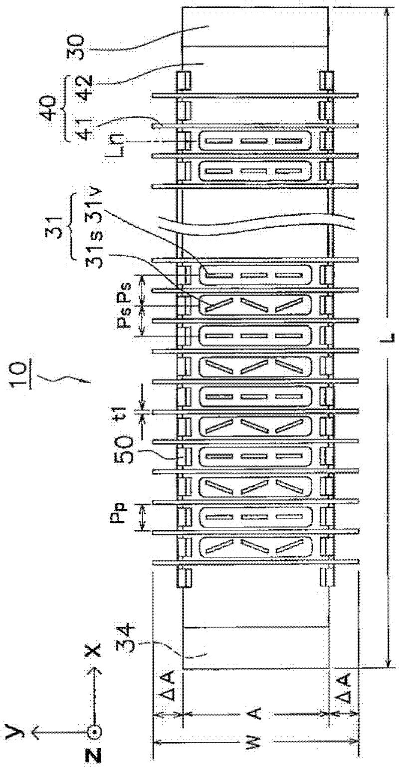
[0050] refer to figure 1 as well as figure 2 The overall configuration of the slot array antenna according to the first embodiment of the present invention will be described. figure 1 It is a perspective view showing the overview of the slot array antenna according to the first embodiment. figure 2 (A) is figure 1 Front view of the slot array antenna, figure 2 (B) is figure 1 Bottom view of the slotted array antenna. image 3 It is a partially broken enlarged front view of one end and the vicinity of the other end of the radiation waveguide 30 .

[0051] figure 1 The shown slot array antenna 10 mainly includes an introduction waveguide 20 , a radiation waveguide 30 , a grid 40 , and a clip 50 . Such as figure 2 As shown in (A), on the waveguide 30 for radiation, the slots 31 for radiation are arranged vertically and horizontally. Electromagnetic waves are radiated from the radiating slit 31 , and the radiation direction of th...

no. 2 Embodiment approach

[0083] (1) overall composition

[0084] refer to Figure 6 as well as Figure 7 The overall configuration of the slot array antenna according to the second embodiment of the present invention will be described. Figure 6 It is a perspective view showing the overview of the slot array antenna according to the second embodiment. Figure 7 (A) is Figure 6 Partially fractured front view of the slotted array antenna, Figure 7 (B) is Figure 7 (A) I-I line sectional view.

[0085] Figure 6 The shown slot array antenna 10A mainly includes an introduction waveguide 20A, a radiation waveguide 30A, a grid 40A, and a clip 50 . In the waveguide 30A for radiation, such as Figure 7 As shown in (A), the radiation slits 36 are arranged vertically and horizontally. The electromagnetic wave is radiated from the radiation slit 36, the radiation direction of the electromagnetic wave from the radiation slit 36 ​​is the z-axis direction, the electromagnetic wave propagation direction i...

no. 3 Embodiment approach

[0120] (1) overall composition

[0121] refer to Figure 14 The overall configuration of the slot array antenna according to the third embodiment of the present invention will be described.

[0122] Figure 14 It is a partial cross-sectional view illustrating the appearance of the slot array antenna according to the third embodiment. exist Figure 14 represents a part of the x-axis direction of the slot array antenna 10B, in Figure 14 The introduction waveguide of the slot array antenna 10B is not shown in FIG. because Figure 14 The configuration of the introduction waveguide of the middle slot array antenna 10B is the same as the configuration of the introduction waveguide 20A of the slot array antenna 10A of the second embodiment, so description and illustration are omitted.

[0123] Like the slot array antenna 10A of the second embodiment, the slot array antenna 10B according to the third embodiment includes a radiation waveguide 30B and a grid 40B. Furthermore, th...


PUM


Abstract

This disclosure provides a slot array antenna, which includes an emission waveguide having a conductor surface where emission slot rows are formed and for guiding electromagnetic waves to be emitted from the emission slot rows, each of the emission slot rows having a plurality of emission slots are arrayed in line, and a lattice. The lattice includes a plurality of conductor walls formed in a planer shape so as to extend in a direction intersecting with the conductor surface and repeatedly arranged corresponding to the plurality of emission slots, and a base plate coupling and fixing the plurality of conductor walls thereto, the base plate being fastened to the conductor surface of the emission waveguide.

Description

technical field [0001] The present invention relates to a slot array antenna used in radar, communication equipment, broadcasting equipment, etc., and a radar device equipped with the slot array antenna. Background technique [0002] A slot array antenna in which a plurality of slots that resonate with transmitting and receiving electromagnetic waves are arranged on the side of the waveguide generally has a characteristic of high side lobe level at low gain. A slot array antenna in which this characteristic is improved is disclosed in Patent Document 1 (International Publication No. 2008 / 018481 pamphlet). [0003] Figure 18 (A) and Figure 18 (B) shows an example of the slot array antenna described in this patent document 1. Figure 18 (A) is a front view showing a configuration example of a slot array antenna according to Patent Document 1, Figure 18 (B) is a bottom view. exist Figure 18 (A) and Figure 18 (B) The circle marked with black dots in the xyz coordinates ind...

Claims


Application Information

Patent Timeline
Patent Type & Authority Applications(China)
IPC IPC(8): H01Q13/22H01Q21/00G01S13/00
CPCH01Q13/22G01S13/9307H01Q21/005G01S7/024G01S13/937
Inventor 宫川哲也箟耕治
Owner FURUNO ELECTRIC CO LTD
Why Eureka
Try Eureka