Follow-up illuminating free stereo video image display

A stereoscopic video image and display technology, applied in stereoscopic systems, image communications, instruments, etc., can solve the problems of large volume, high cost, and unsuitability for multiple people to watch the display

Inactive Publication Date: 2012-03-28
NANKAI UNIV
View PDF6 Cites 12 Cited by
  • Summary
  • Abstract
  • Description
  • Claims
  • Application Information

AI Technical Summary

Problems solved by technology

[0002] At present, the display device is transitioning from the flat display mode to the stereoscopic display mode, and the liquid crystal light valve stereoscopic TV has begun to be commercialized, which can produce very good stereoscopic video images, but there are also some disadvantages: each viewer wears special glasses, By receiving the synchronous signal from the display, controlling the high-speed switch of the left and right liquid crystal light valves to obtain a three-dimensional image, all viewers must wear this kind of glasses to watch; the glasses are mainly composed of liquid crystal light valves, receiving control circuits, battery frames, etc. Heavier than ordinary glasses, it is easy to fatigue after long-term use; viewers who usually wear ordinary corrected vision glasses need to wear double-layer glasses to watch, and are more prone to fatigue; glasses need battery power supply, and the battery has a certain life, which affects the continuity of use; the cost of glasses is compared High, one payment per person, difficult for many ordinar

Method used


Image

  • Follow-up illuminating free stereo video image display
  • Follow-up illuminating free stereo video image display
  • Follow-up illuminating free stereo video image display

Examples


Embodiment 1

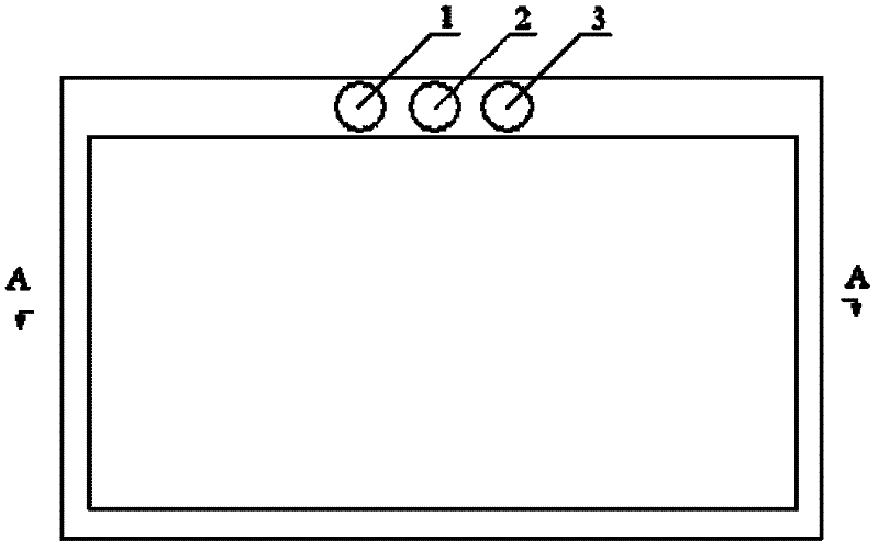
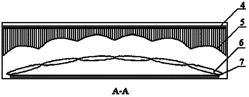
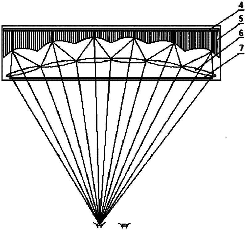
[0076] Such as figure 1 , 2 As shown, the autostereoscopic video image display based on follow-up lighting provided by the present invention includes a housing, a light source array 4 installed in the housing, a laminated light guide plate 5, a cylindrical lens array 6, a transmissive liquid crystal screen 7, and an infrared camera 2. Infrared lighting sources 1 and 3.

[0077] The light source array is arranged at the rear of the display, and each light source in the light source array is arranged on the same plane;

[0078] The laminated light guide plate is arranged in front of the light source array, and each light guide plate in the laminated light guide plate is made of a transparent flat sheet, and the adjacent light guide plates are separated by an opaque film; the light guide plate is perpendicular to the plane where the light source array is located, And perpendicular to the horizontal plane, the envelope surface of the end envelope of the laminated light guide pl...


PUM


Abstract

A follow-up illuminating free stereo video image display is disclosed. The display comprises: an audience pupil position acquisition apparatus (an infrared source and an infrared camera), which is used to collect left and right pupil position information of all the audiences and does not affect the audiences to watch an image; an image display device (a transmission-type liquid crystal display), which is used to display the externally input left and right video images in a time sharing mode; a back-light follow-up lighting device (comprising a light source array, a laminated light guide plateand a cylindrical surface lens array), which is used to divide a backlight lighting beam into left and right two beams so as to achieve alternative illumination, wherein one beam follows movement of the left pupils of the audiences and the other beam follows the movement of the right pupils of the audiences. The beams and the left and right video images which are displayed in the time sharing mode are switched synchronously. The left image is projected to the left pupils of all the audiences and the right image is projected to the right pupils of all the audiences so that the audiences can watch the video stereo images without crosstalk. The audiences can independently set a 2D or a 3D mode. The highest transverse resolution is a physical resolution of the liquid crystal screen.

Description

technical field [0001] The invention belongs to the field of autostereoscopic display technology, and relates to the optimized design of a non-coaxial optical system, rapid identification and positioning of multiple targets, rapid grouping of targets, follow-up lighting control, and synchronous control of image display and lighting. Background technique [0002] At present, the display device is transitioning from the flat display mode to the stereoscopic display mode, and the liquid crystal light valve stereoscopic TV has begun to be commercialized, which can produce very good stereoscopic video images, but there are also some disadvantages: each viewer wears special glasses, By receiving the synchronous signal from the display, controlling the high-speed switch of the left and right liquid crystal light valves to obtain a three-dimensional image, all viewers must wear this kind of glasses to watch; the glasses are mainly composed of liquid crystal light valves, receiving co...

Claims


Application Information

Patent Timeline
IPC IPC(8): H04N13/00G02B27/22
Inventor 黄大刚代煜张建勋李彬
Owner NANKAI UNIV
Why Eureka
Try Eureka