
Drying apparatus

A drying equipment and drying technology, applied in the direction of tobacco drying, heat recovery system, drying gas arrangement, etc., can solve the problems of low temperature of recovered energy and little benefit of the system, etc.

Inactive Publication Date: 2012-03-28
DICKINSON LEGG
View PDF6 Cites 7 Cited by
  • Summary
  • Abstract
  • Description
  • Claims
  • Application Information

AI Technical Summary

Problems solved by technology

However, the temperature of the recovered energy is lower and does not provide much benefit to the system

Method used


Image

  • Drying apparatus
  • Drying apparatus
  • Drying apparatus

Examples


Embodiment Construction

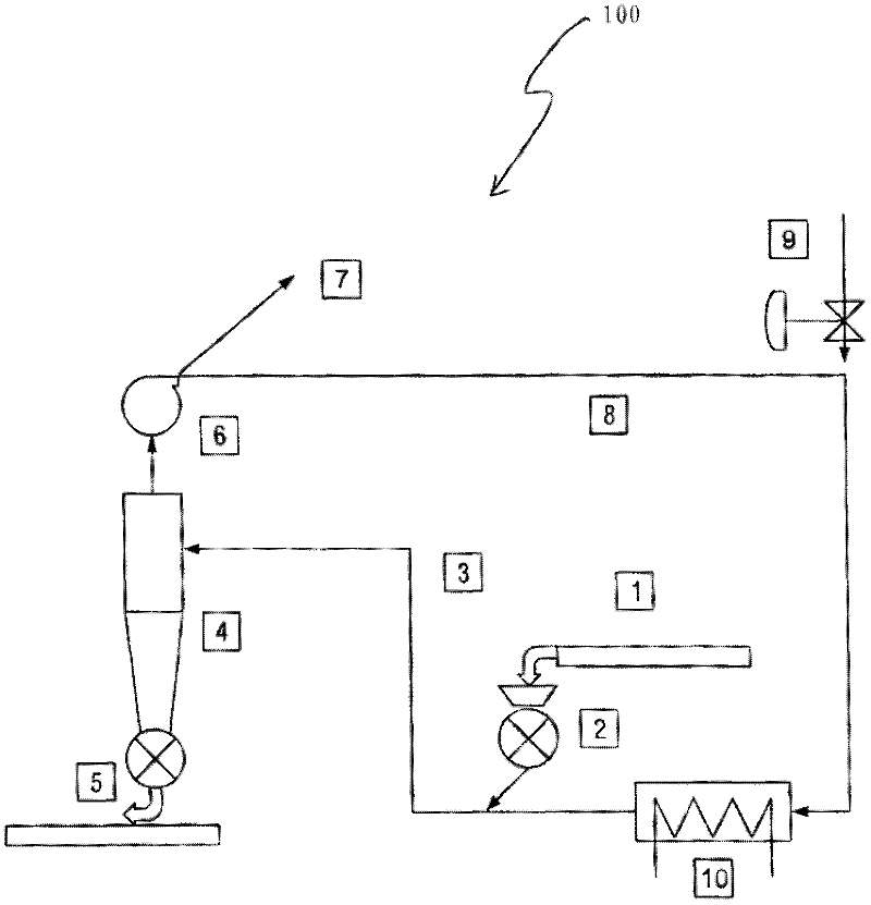
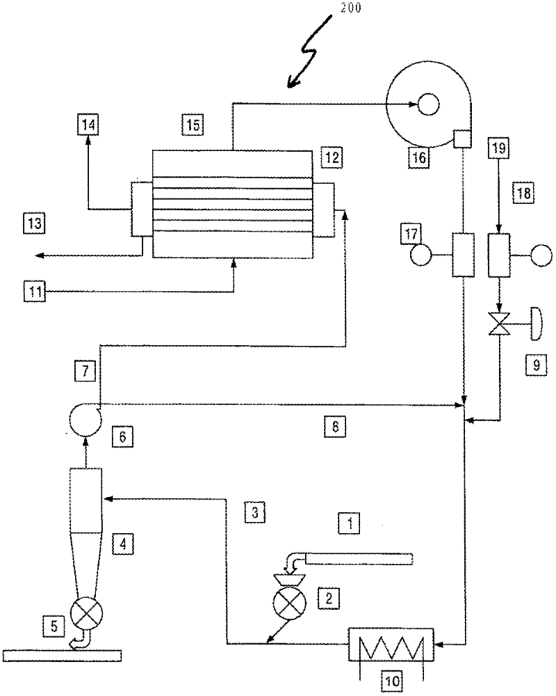
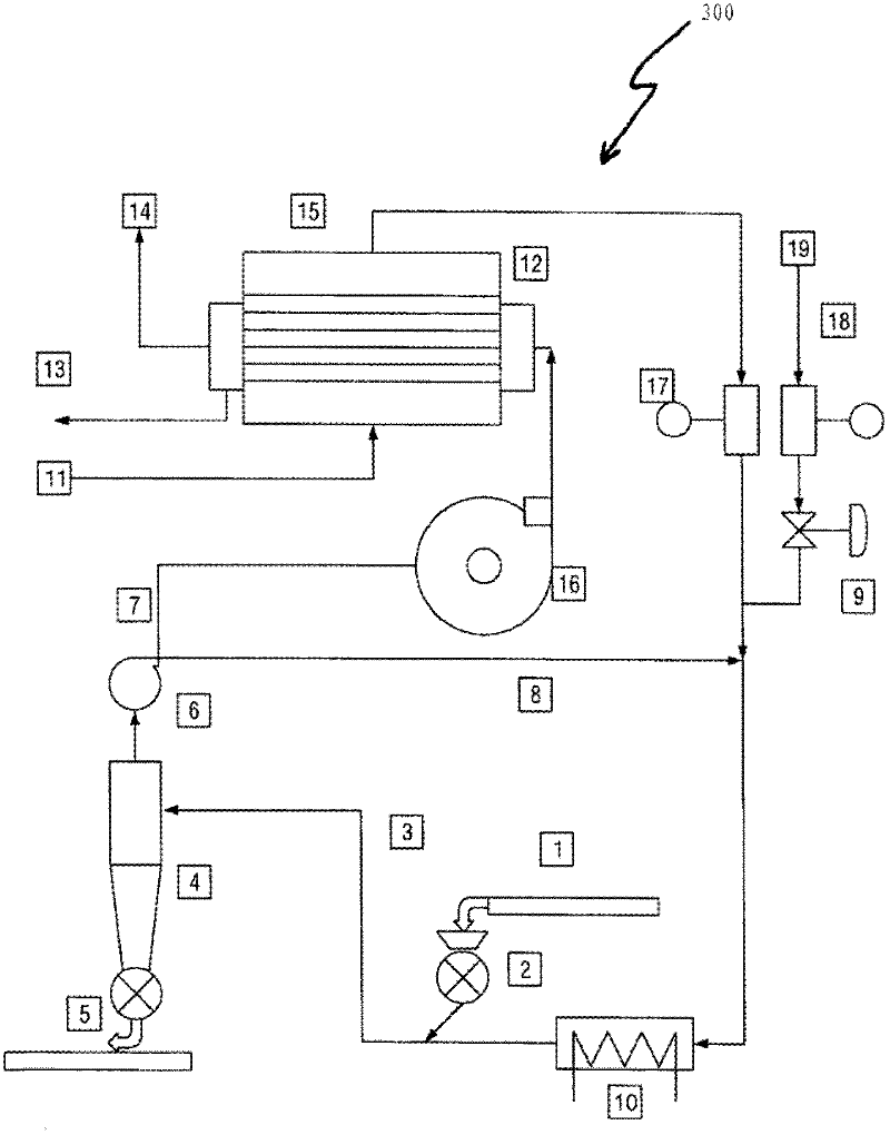
[0022] will now refer to figure 1 , 2 and 3 to describe a conventionally known drying equipment and the drying equipment of the present invention. Some details of the structure and method of operation of known drying apparatuses have been given above and the details are summarized below. Moisture is removed from the moist tobacco product in the duct 3 where the tobacco product is conveyed and dispersed in a superheated air stream. A cyclone operates to separate the tobacco product from the exhaust gas which can then be processed and purified or recycled.

[0023] The drying apparatus 200, 300 of the first and second embodiments of the present invention comprises substantially similar figure 1 Some parts of the device shown, thus similar features, are labeled with the same reference numerals. Refer to the attached figure 2 , which shows a drying device 200 according to a first embodiment of the present invention. However, if figure 2 As shown, the drying equipment of t...


PUM


Abstract

A drying apparatus for drying a fibrous material is described. The drying apparatus comprises a heater arranged to heat a first gas stream and a fibrous material, the first gas stream is arranged to enter the drying apparatus at an inlet, the gas stream including steam, a separator for separating a said fibrous material from the first gas stream to form a second gas stream. The drying apparatus further includes a heat exchanger arranged to condense and separate a steam component and a water component from the second gas stream, and a compressor arranged to compress the steam component and return the steam component to the inlet.; In an alternative the compressor is arranged to compress the second gas stream directly and before the heat exchanger arranged to condense and separate a steam component and a water component from the second gas stream, and return the steam component to the inlet. A method of drying is also described. The invention as disclosed seeks to recover the energy content of the exhaust from the drying apparatus and return this to the dryer for re-use.

Description

technical field [0001] The present invention relates to drying apparatus and methods for drying fibrous material, in particular but not limited to drying apparatus and methods for drying fibrous material such as tobacco leaves or parts of tobacco leaves. Background technique [0002] In major tobacco processing, cigarettes are manufactured by processing tobacco leaves. The laminated tobacco leaf sections are compressed and then cut in a cutting machine to produce tobacco shreds suitable for cigarette manufacture. Typically, moisture is removed from the fibrous tobacco material to improve the handling and filling properties of the tobacco material. [0003] It is known in the tobacco industry to use pneumatic conveying dryers, also known as airflow dryers, to reduce the moisture content of cigarette filler material to levels eg suitable for cigarette manufacture and packaging. The general principle in such dryers is to transport the tobacco product along the channels by mea...

Claims


Application Information

Patent Timeline
Patent Type & Authority Applications(China)
IPC IPC(8): F26B17/10F26B21/08F26B23/00
CPCY02B30/52F26B2200/22F26B23/004F26B17/107A24B3/04Y02B30/123Y02P70/10Y02P70/50
Inventor T.H.怀特A.D.詹姆斯M.法瓦罗
Owner DICKINSON LEGG
Learn More