
Micropressure pot

A technology of pressure relief valve and pot cover, applied in cooking utensils, household utensils, applications and other directions, can solve the problems of inconvenience in daily life, long time for stewing dishes or soup, taking away nutrients, etc., to improve heating efficiency and energy Utilization rate, the effect of shortening the time of stewing dishes or soup, and improving the heat preservation performance

Inactive Publication Date: 2012-04-04
ZHEJIANG COOKER KING COOKER
View PDF7 Cites 6 Cited by
  • Summary
  • Abstract
  • Description
  • Claims
  • Application Information

AI Technical Summary

Problems solved by technology

[0003] One is that in order to drink delicious thick soup, it takes too long to prepare and wait. In addition, due to the work under normal pressure, a large amount of water vapor will be discharged outside, which will cause too much water loss in the pot and take away some nutrients. Take care of the soup pot to prevent accidents such as overflow and dry pot, which will bring great inconvenience to the soup pot
[0004] The second is that due to working under normal pressure, it takes longer to cook dishes or soup in plateau areas, which brings a lot of inconvenience to daily life
[0005] The third is to stew dishes or soup for a long time, some nutrients with poor thermal stability will be destroyed, which is a waste of energy, not environmentally friendly, and does not conform to the energy-saving and emission-reduction policies advocated by the state
[0006] For this reason, many manufacturers and people of insight are developing and researching on the above-mentioned problems, but there is no ideal product coming out so far.

Method used


Image

  • Micropressure pot
  • Micropressure pot
  • Micropressure pot

Examples


Embodiment Construction

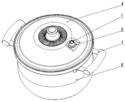
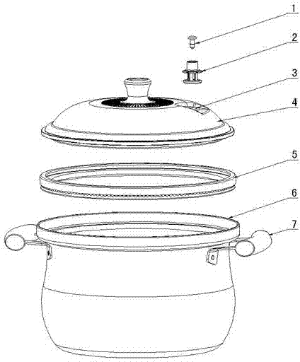
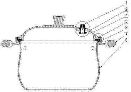
[0025] Figure 1 to Figure 5 Shown, for the specific embodiment that the present invention creates micro pressure cooker, it comprises pot body 6, pot cover 4, sealing ring 5, and described pot cover 4 is preferably made of glass or purple sand material, makes pot cover 4 have With a certain weight, the size of the slight pressure in the pot depends on the weight of the pot cover 4. The pot body 6 is provided with a reverse side step 8, and the pot cover 4 is provided with a pot cover convex edge 14 and a right angle On the side, the pot cover 4 is provided with an air vent 11, the pot body 6 is fixed with a handle 7, and the sealing ring 5 is provided with an inner card slot with an inward opening and a V-shaped mouth 17 with an outward opening. , the inner card slot of the sealing ring 5 is buckled on the flange 14 of the pot cover, the inner side of the V-shaped mouth 17 is on the right-angled edge of the pot cover 4, and the upper bottom surface of the V-shaped mouth 17 is...


PUM


Abstract

The invention discloses a micropressure pot. The micropressure pot comprises a pot body (6), a pot cover (4) and a seal ring (5), wherein reverse side steps (8) are arranged on the pot body (6); a pot cover protruding side (14) matched with the reverse side steps (8) and a right angle side are arranged on the pot cover(4); an air hole (11) is arranged on the pot cover (4); and an inner clamping groove opened inward and a V-shaped mouth (17) opened outward are arranged on the seal ring (5); the inner clamping groove of the seal ring (5) is clamped on the pot cover protruding side(14); the inner side of the V-shaped mouth (17) is pressed on the right angle side of the pot cover (4); the upper bottom surface of the V-shaped mouth (17) is a plane; two circles of inner-outer circle small protruding points (15 and 16) which are uniformly and circumferentially distributed and mutually staggered and have the same height respectively are arranged on the plane; and an inclined surface of the V-shaped mouth (17) is a sealing surface (18) which is matched with the reverse side steps (8) of the pot body (6). Due to the adoption of the structure, the micropressure pot has the advantages of simple and reasonable structure, short soup-stewing time, energy saving, emission reduction and the like, is convenient to use and operate and runs safely and reliably.

Description

technical field [0001] The invention relates to a cooking utensil, in particular to a micro-pressure cooker used for stewing, boiling, boiling and soup making in families, restaurants and hotels. Background technique [0002] With the development of our country's economy and social progress, fundamental changes have taken place in residents' economic income and living standards, and people attach great importance to dietary structure and nutritional balance. Stewed dishes and soups have become the most nutritious and most delicious food. Delicious, one of the most popular public food. The pot currently on the market is generally composed of a pot body and a pot cover. The pot body is provided with a reverse side step, and the pot cover is provided with a pot cover convex edge matched with the reverse side step. The exhaust method adopts the direct exhaust type, that is, one or more vent holes are set on the pot cover, and the steam is directly discharged out of the pot thro...

Claims


Application Information

Patent Timeline
IPC IPC(8): A47J27/00
Inventor 王鹏
Owner ZHEJIANG COOKER KING COOKER
Learn More