Composite die for edge cutting and punching

A composite mold, edge trimming and punching technology, applied in the field of trimming and punching molds, can solve the problems of low processing efficiency, high labor intensity and high production cost, and achieve high production efficiency, labor intensity reduction, and production cost reduction. Effect

Inactive Publication Date: 2012-04-04
TONGLING BAIRUIHAO TECH
View PDF8 Cites 11 Cited by
  • Summary
  • Abstract
  • Description
  • Claims
  • Application Information

AI Technical Summary

Problems solved by technology

[0002] For the workpiece of the idler cylinder that needs to be trimmed and punched, it generally needs to go through three processes. First, the parts are trimmed on the trimming machine, then punched, and finally placed in the shaping machine for shaping, eliminating the need for trimming and punching. The impact of punching on parts, so that not only three processes are required, but also a lot of equipment is required, resulting in long production lines, high labor intensity, low productivity and high production costs
In order to solve the above technical problems, some people have designed a mold that completes punching, trimming, and shaping at one time, but the structural design is unreasonable, resulting in poor processing efficiency of parts and low processing efficiency.

Method used


Image

  • Composite die for edge cutting and punching
  • Composite die for edge cutting and punching

Examples


Embodiment Construction

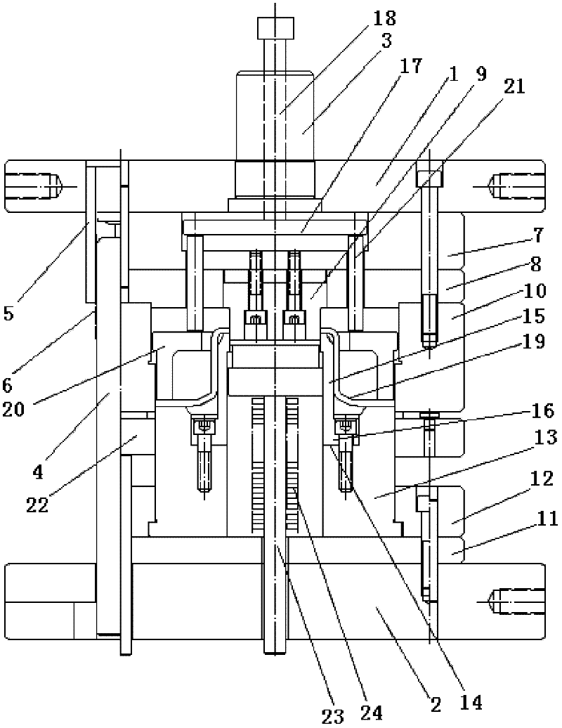
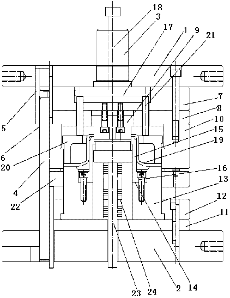
[0010] Referring to the accompanying drawings, the trimming and punching composite mold includes an upper template 1 and a lower template 2, and an upper mold handle 3 is fixedly installed on the upper template 1, and guide posts 4 that slide and cooperate with each other are respectively fixed between the upper template and the lower template. , guide sleeve 5, a ball 6 is arranged between the guide post and the guide sleeve, a punch backing plate 7, a punch fixing plate 8 are fixedly installed on the lower end surface of the upper template 1 in sequence, the center and edge of the punch fixing plate 8 are Punching punch 9 and edge trimming die 10 are respectively fixedly installed at each place, die backing plate 11 and die fixing plate 12 are fixed on the upper end surface of lower template 2, and edge trimming punch 13 is fixedly installed in the die fixing plate 12, A step 14 is provided in the trimming punch 13, and a punching die 15 is fixedly installed on the step of th...


PUM


Abstract

The invention discloses a composite die for edge trimming and punching, comprising an upper die plate, a lower die plate, an upper die shank being fixedly mounted on the upper die plate, and a guide pillar and a guide sleeve in sliding fit being respectively fixed between the upper die plate and the lower die plate. The lower end face of the upper die plate is fixedly mounted with a male die backup plate and a male die dead plate successively. The lower center and the edge of the male die dead plate are fixedly mounted with a punching male die and an edge cutting female die. The upper end face of the lower die plate is fixed with a female die backup plate and a female die dead plate. An edge cutting male die which is provide with steps inside is fixedly mounted in the female die dead plate. A punching female die which has a turnup at the lower end is fixedly mounted on the steps of the cutting edge female die. The invention integrates edge cutting and punching into one die, which shortens production line, reduces labor intensity, raises working efficiency and lowers production cost.

Description

technical field [0001] The invention relates to a trimming and punching die, in particular to a composite die for trimming and punching a cylinder body of an idler roller. Background technique [0002] For the workpiece of the idler cylinder that needs to be trimmed and punched, it generally needs to go through three processes. First, the parts are trimmed on the trimming machine, then punched, and finally placed in the shaping machine for shaping, eliminating the need for trimming and punching. The impact of punching on parts can not only require three processes, but also require a lot of equipment, resulting in long production lines, high labor intensity, low productivity and high production costs. In order to solve the above technical problems, someone has designed a mold that can punch holes, cut edges, and shape at one time, but the structural design is unreasonable, resulting in poor processing efficiency of parts and low processing efficiency. Contents of the invent...

Claims


Application Information

Patent Timeline
Patent Type & Authority Applications(China)
IPC IPC(8): B21D37/10B21D28/14B21D28/34
Inventor 宇尔荣宗高进余登思
Owner TONGLING BAIRUIHAO TECH
Why Eureka
Try Eureka