
Machining technology and machining equipment for riveting base boards and caster axles of oil heaters

A processing equipment and foot plate technology, which is applied in the field of processing equipment for riveting the oil base plate and caster shaft, can solve the problems of high stamping risk, high product scrap rate, long production line and other problems of the stamping machine, so as to shorten the production line and reduce handling The effect of reducing the number of times and reducing manual input

Inactive Publication Date: 2013-11-20
NINGBO SINGFUN ELECTRIC APPLIANCE
View PDF5 Cites 5 Cited by
  • Summary
  • Abstract
  • Description
  • Claims
  • Application Information

AI Technical Summary

Problems solved by technology

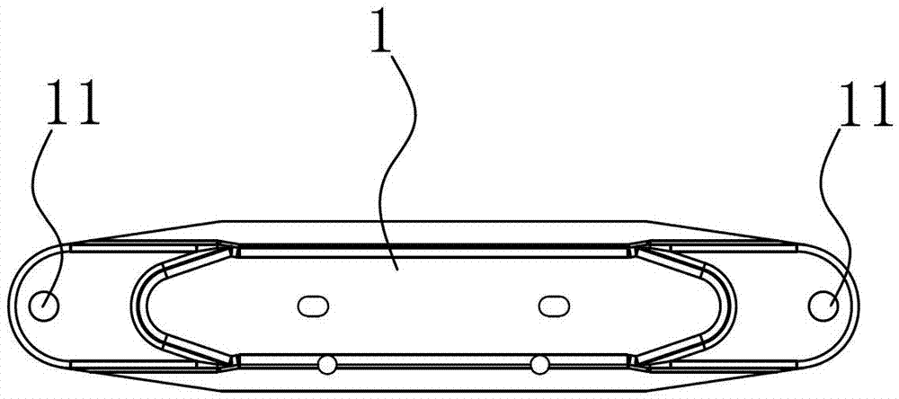
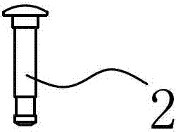
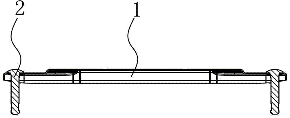
[0002] The electric oil heater is also called the oil-filled heater. The appearance is similar to that of the radiator. It is a safe and reliable space heater. It mainly includes a radiator composed of multiple radiators, a control panel and casters. The current electric heater For the convenience of moving the bottom, there are many such casters. The casters are connected to the radiator through the foot plate assembly. The foot plate assembly consists of the foot plate body and the caster shaft riveted on the foot plate body. At present, the foot plate body and the caster shaft are mostly riveted manually, which requires manual work by workers. Put a caster shaft into a riveting hole of the foot board body, and then put it into the punching machine for stamping. The production line is long, and the semi-finished product needs to be transported many times. Since there are two caster shafts on the foot board assembly, workers need to operate twice consecutively. , the efficiency is low, and at the same time, the workers manually operate the stamping machine with high risk of stamping, and the product scrap rate is high, so that the production cost is greatly increased

Method used


Image

  • Machining technology and machining equipment for riveting base boards and caster axles of oil heaters
  • Machining technology and machining equipment for riveting base boards and caster axles of oil heaters
  • Machining technology and machining equipment for riveting base boards and caster axles of oil heaters

Examples


Embodiment Construction

[0027] see Figure 1 to Figure 4 According to the processing technology of riveting the oil base plate and the caster shaft provided by the present invention, it mainly includes the following steps:

[0028] (1) Send the foot plate body 1 made by the continuous stamping die to the automatic feeder 3, and the automatic feeder 3 pushes the foot plate body 1 to the assembly station, and stops intermittently.

[0029] (2) The caster shaft 2 is sent to the assembly station through the vibrating plate 4, and when step (1) pauses intermittently, the caster shaft 2 is inserted into the riveting hole 11 of the foot plate body 1 under the action of the vibrating plate 4, and the riveted end It is located at the riveting hole 11 to form a foot plate assembly.

[0030] (3) The automatic feeder 3 sends the foot plate assembly to the lifting trampoline of the automatic riveting machine 5, the upper template 51 of the automatic riveting machine 5 descends and docks with the lower template 5...


PUM


Abstract

The invention discloses machining equipment for riveting base boards and caster axles of oil heaters. The machining equipment comprises an automatic riveting machine, a vibration disc and an automatic loading machine. The vibration disc is used for assembling caster axles and a base board body to form a base board combination, and the automatic loading machine is used for conveying the base board combination to the automatic riveting machine and penetrates the automatic riveting machine and the vibration disc. The machining equipment for riveting the base boards and the caster axles of the oil heaters has the advantages that the base board combination can be assembled, automatically loaded, riveted and unloaded under the matched actions of the vibration disc, the automatic loading machine and the automatic riveting machine, only the caster axles need to be placed into the vibration disc, and the base board body is placed into the automatic loading machine, so that the base board combination can be assembled, automatically loaded, riveted and unloaded without being repeatedly carried, the base board combination carrying frequency and the labor input are reduced, an assembly line is shortened, the production efficiency is improved for products, the yield of the products is increased, the labor intensity of workers is reduced, and the production cost is lowered.

Description

technical field [0001] The invention relates to a processing technology for riveting the oil base plate and the caster shaft, and also designs a processing equipment for riveting the oil base plate and the caster shaft. Background technique [0002] The electric oil heater is also called the oil-filled heater. The appearance is similar to that of the radiator. It is a safe and reliable space heater. It mainly includes a radiator composed of multiple radiators, a control panel and casters. The current electric heater For the convenience of moving the bottom, there are many such casters. The casters are connected to the radiator through the foot plate assembly. The foot plate assembly consists of the foot plate body and the caster shaft riveted on the foot plate body. At present, the foot plate body and the caster shaft are mostly riveted manually, which requires manual work by workers. Put a caster shaft into a riveting hole of the foot board body, and then put it into the pu...

Claims


Application Information

Patent Timeline
Patent Type & Authority Applications(China)
IPC IPC(8): B21D39/00B21D43/02
Inventor 姚国宁赵仁壮何惠平韩亚辉钟平
Owner NINGBO SINGFUN ELECTRIC APPLIANCE
Learn More