Die casting machine punch
A die-casting machine and punch technology, which is applied in the field of mechanical parts manufacturing, can solve the problems of fewer punches, serious wear of punches, and inconspicuous improvement, so as to increase the durability of punches, reduce the amount of wear of punches, and reduce production costs Effect
- Summary
- Abstract
- Description
- Claims
- Application Information
AI Technical Summary
Problems solved by technology
Method used
Image


Examples
Embodiment 1
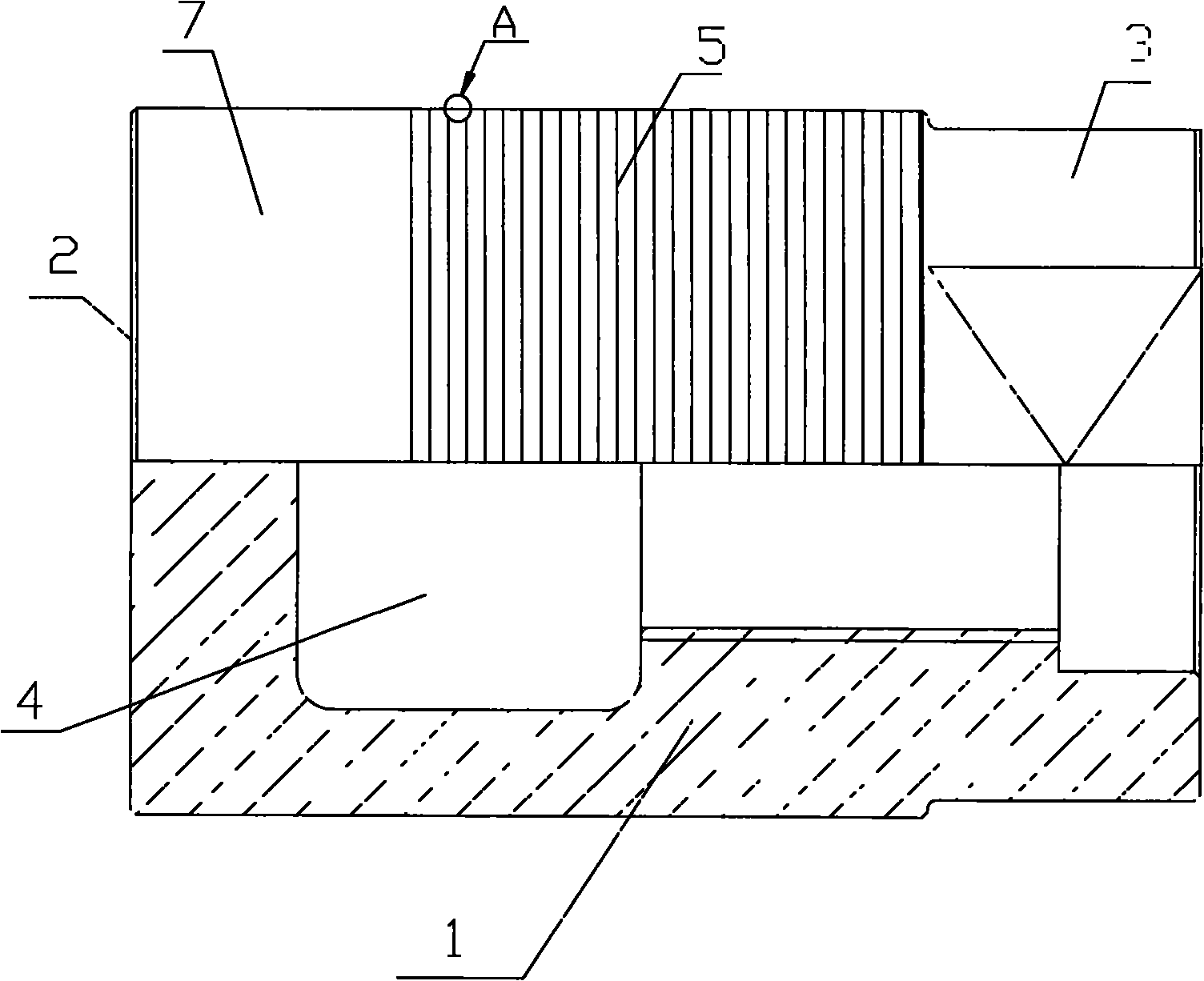
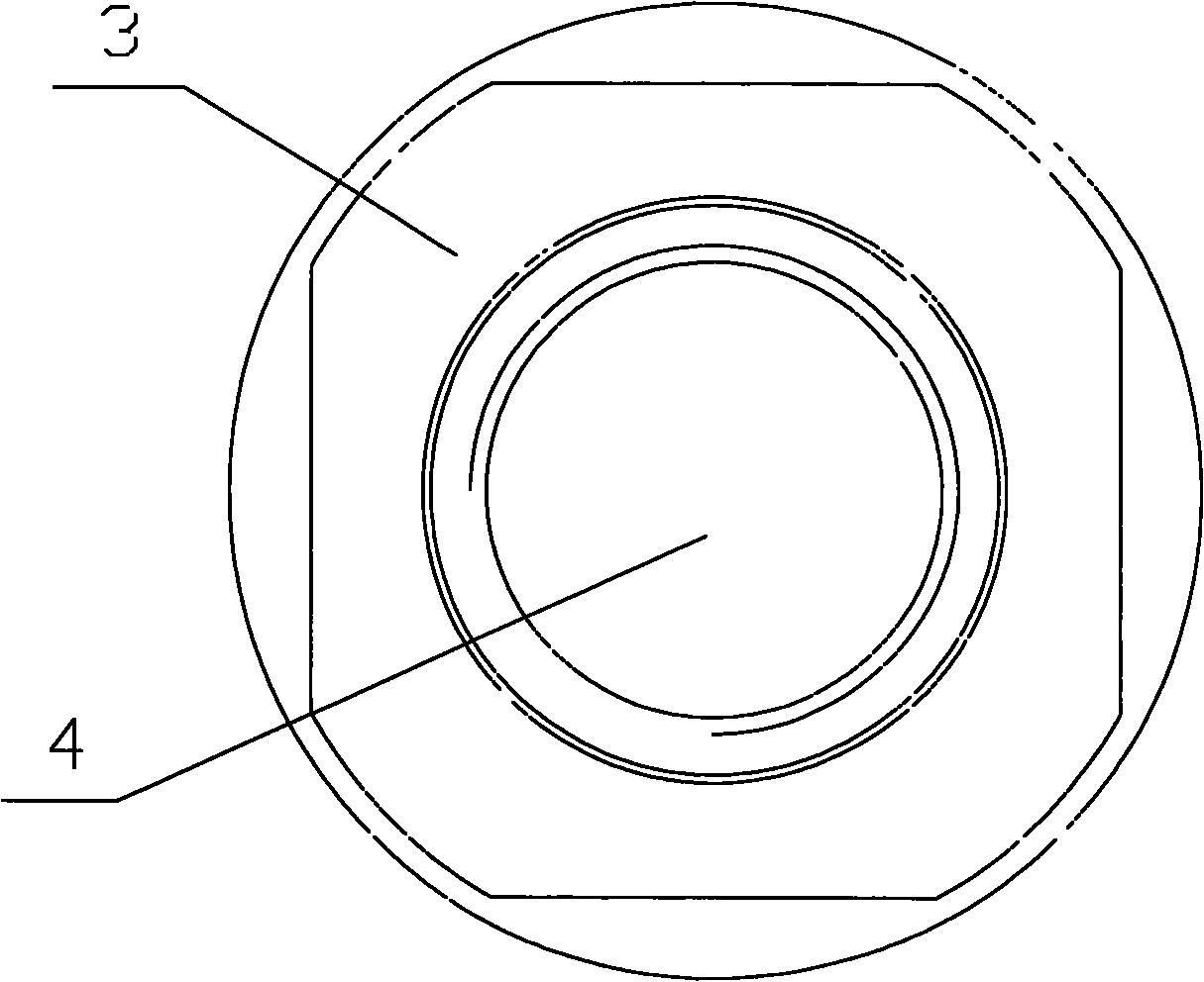
[0020] Such as figure 1 , figure 2 , image 3 As shown, a die-casting machine punch includes a punch body 1, an injection part 2 is provided at one end of the punch body 1 in the axial direction, and a connecting part 3 is provided at the other end. The axial center of the punch body 1 A cooling cavity 4 is provided, and a lubricating part 5 and a smoothing part 7 are provided on the radially outer surface of the punch body 1 . The lubricating part 5 is composed of a plurality of oil grooves 6 arranged at intervals on the radially outer surface of the punch body 1 , and one or both ends of the lubricating part 5 are smooth parts 7 . The lubricating portion 5 has a width of 0.657 of the width of the radial outer surface of the punch body 1 and a surface roughness of 0.8 μm. The lubricating part 5 is provided with oil grooves 6 arranged at intervals of 1 mm. The cross section of the oil grooves 6 is arc-shaped, the width of the oil grooves 6 is 0.25 mm, and the depth of the ...
Embodiment 2
[0022] A die-casting machine punch, the punch includes a punch body, an injection part is provided at one axial end of the punch body, a connecting part is provided at the other end, a cooling cavity is provided at the axial center of the punch body, the punch body The radially outer surface of the body is provided with a lubricating portion. The lubricating part is composed of a plurality of oil grooves arranged at intervals on the radially outer surface of the punch body. The lubricating part is arranged between the injection part and the connecting part, covering the entire radially outer surface of the punch body. The surface roughness of the lubrication portion was 0.8 μm. The oil grooves that make up the lubricating part are arranged at a pitch of 1 mm. The cross section of the oil grooves is arc-shaped, the width of the oil grooves is 0.3 mm, and the depth of the oil grooves is 0.01 mm.
Embodiment 3
[0024] A die-casting machine punch, the punch includes a punch body, an injection part is provided at one axial end of the punch body, a connecting part is provided at the other end, a cooling cavity is provided at the axial center of the punch body, the punch body The radially outer surface of the body is provided with a lubricating portion. The lubricating part is composed of an oil groove arranged on the radially outer surface of the punch body. The cross section of the oil groove is rectangular, and one or both ends of the lubricating part are smooth parts. The width of the oil groove is 0.45 of the radial outer surface width of the punch body, and the surface roughness of the oil groove is 0.8 μm. The oil groove depth is 0.1mm.
PUM
| Property | Measurement | Unit |
|---|---|---|
| Surface roughness | aaaaa | aaaaa |
| Width | aaaaa | aaaaa |
| Surface roughness | aaaaa | aaaaa |
Abstract
Description
Claims
Application Information
 - R&D
- Intellectual Property
- Life Sciences
- Materials
- Tech Scout
- Unparalleled Data Quality
- Higher Quality Content
- 60% Fewer Hallucinations
Browse by: Latest US Patents, China's latest patents, Technical Efficacy Thesaurus, Application Domain, Technology Topic, Popular Technical Reports.
© 2025 PatSnap. All rights reserved.Legal|Privacy policy|Modern Slavery Act Transparency Statement|Sitemap|About US| Contact US: help@patsnap.com