
System and method for treating coal direct liquefaction residue

A coal liquefaction residue and coal direct liquefaction technology, which is applied in the preparation of liquid hydrocarbon mixtures and the petroleum industry, can solve problems such as low reliability, complicated operation, and difficult separation, and achieve high reliability and high separation efficiency.

Active Publication Date: 2012-04-04
CHNA ENERGY INVESTMENT CORP LTD +3
View PDF11 Cites 29 Cited by
  • Summary
  • Abstract
  • Description
  • Claims
  • Application Information

AI Technical Summary

Problems solved by technology

Chinese patents CN101962561A and CN101962560A have basically the same idea. Solvent extraction is carried out on the liquefied residue first, and then solid-liquid and liquid-liquid separation are carried out, but the extraction routes are different, but neither of them gives a specific scheme for the solid-liquid separation of the extraction mixture.
However, at present, there are few studies on the separation of solid-liquid systems after solvent extraction. Chinese patents CN101962561A and CN101962560A only slightly mention that Kerr-MCGEE of the United States and ITSL of Lummus, which are mainly engaged in the research of solid separation in various coal liquefaction products The process uses a gravity settler to separate the system, and the efficiency is relatively low
The separation characteristics of this system are similar to the solid-liquid system of vacuum flash evaporation (reduced pressure distillation), and the separation is relatively difficult. Traditional methods such as filters and centrifuges have disadvantages such as complicated operation, high cost, and low reliability. At the same time, the separation efficiency here requires Try to improve it, and it is not suitable to use the flash evaporation method

Method used


Image

  • System and method for treating coal direct liquefaction residue
  • System and method for treating coal direct liquefaction residue
  • System and method for treating coal direct liquefaction residue

Examples


Embodiment Construction

[0054] In the present invention, all the embodiments, implementations and features of the present invention can be combined with each other under the condition of no contradiction or conflict.

[0055] In the present invention, all equipment, devices, components, etc. can be purchased commercially, or can be self-made according to the content disclosed in the present invention.

[0056] In the present invention, in order to highlight the key points of the present invention, some conventional operations, equipment, devices and components are omitted or simply described.

[0057] In the present invention, "connected to" or "connected to" or "communicated" can mean that the two are directly connected, or can be connected through common components or devices (such as valves, pumps, heat exchangers, etc.) or connect.

[0058] In the present invention, "coal direct liquefaction residue" and "coal liquefaction residue" can be used interchangeably, and both refer to the coal liquefac...


PUM


Abstract

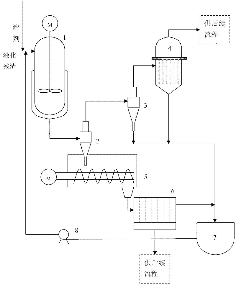
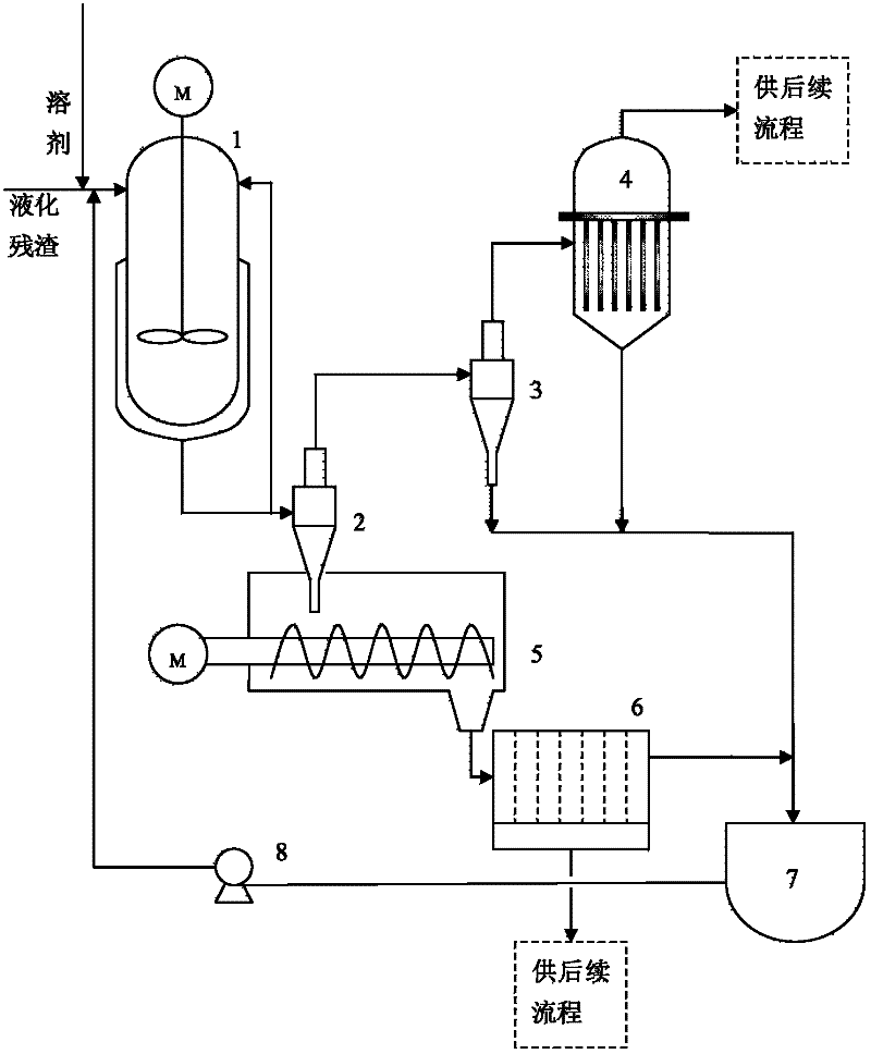
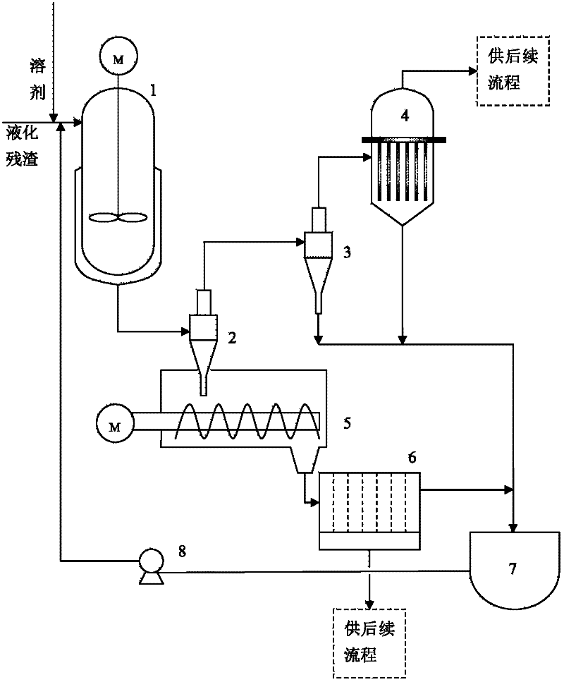
The invention relates to a system and a method for treating coal direct liquefaction residue. The system comprises a mixer (A), a micro cyclone separation unit (B), a filter (C) and an optional precision filter (D), wherein the mixer (A) is at least provided with an extracting solvent inlet, a coal direct liquefaction residue inlet and a coal liquefaction residue extracting mixture outlet; the micro cyclone separation unit (B) is at least provided with a coal liquefaction residue extracting mixture inlet connected to the coal liquefaction residue extracting mixture outlet, a concentrated coal liquefaction residue underflow outlet and a clarified liquid phase mixture outlet; the filter (C) is at least provided with a concentrated coal liquefaction residue underflow inlet connected to the concentrated coal liquefaction residue underflow outlet, and a filtrate outlet; and the optional precision filter (D) is at least provided with a clarified liquid phase mixture inlet connected to the clarified liquid phase mixture outlet, a precision clarified filtrate outlet and a precision filtered intercepting phase outlet. The invention also relates to the method for treating the coal direct liquefaction residue. The method and the system are high in reliability and high in separation efficiency.

Description

technical field [0001] The present invention relates to a treatment method for direct coal liquefaction residue, in particular to a method for solid-liquid separation of fully extracted coal direct liquefaction residue, which belongs to the technical field of solid / liquid separation and is suitable for processing vacuum flash ( or vacuum distillation) coal direct liquefaction residue, the micro-cyclone separation is also suitable for processing the solvent residue solid-liquid system after extraction in other coal direct liquefaction processes. Specifically, the present invention provides a method and system for strengthening the treatment of coal direct liquefaction residue by coupling a micro-cyclone separator and a solvent extraction method. Background technique [0002] Coal direct liquefaction technology is to pyrolyze the coal in the high-concentration coal slurry under high temperature and high pressure, hydrogenate and further decompose under the action of a catalyst...

Claims


Application Information

Patent Timeline
IPC IPC(8): C10G1/00C10G1/04
Inventor 李志明李克健杨强张胜振汪华林吴秀章吕文杰章序文王剑刚李永伦
Owner CHNA ENERGY INVESTMENT CORP LTD
Learn More