Vortex Compressor

A scroll compressor and compression mechanism technology, applied in the field of scroll compressors, can solve problems such as performance degradation

Active Publication Date: 2012-04-04
HITACHI JOHNSON CONTROLS AIR CONDITIONING INC
View PDF6 Cites 13 Cited by
  • Summary
  • Abstract
  • Description
  • Claims
  • Application Information

AI Technical Summary

Problems solved by technology

The re-expansion and re-compression of the compressed gas is caused by the gas entering an...

Method used


Image

  • Vortex Compressor
  • Vortex Compressor
  • Vortex Compressor

Examples


Embodiment 1

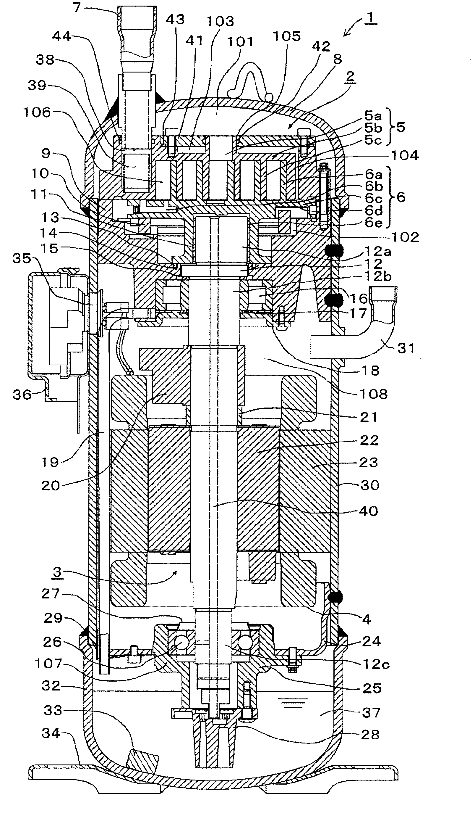
[0071] use figure 1 and figure 2 A scroll compressor according to a first embodiment of the present invention will be described.

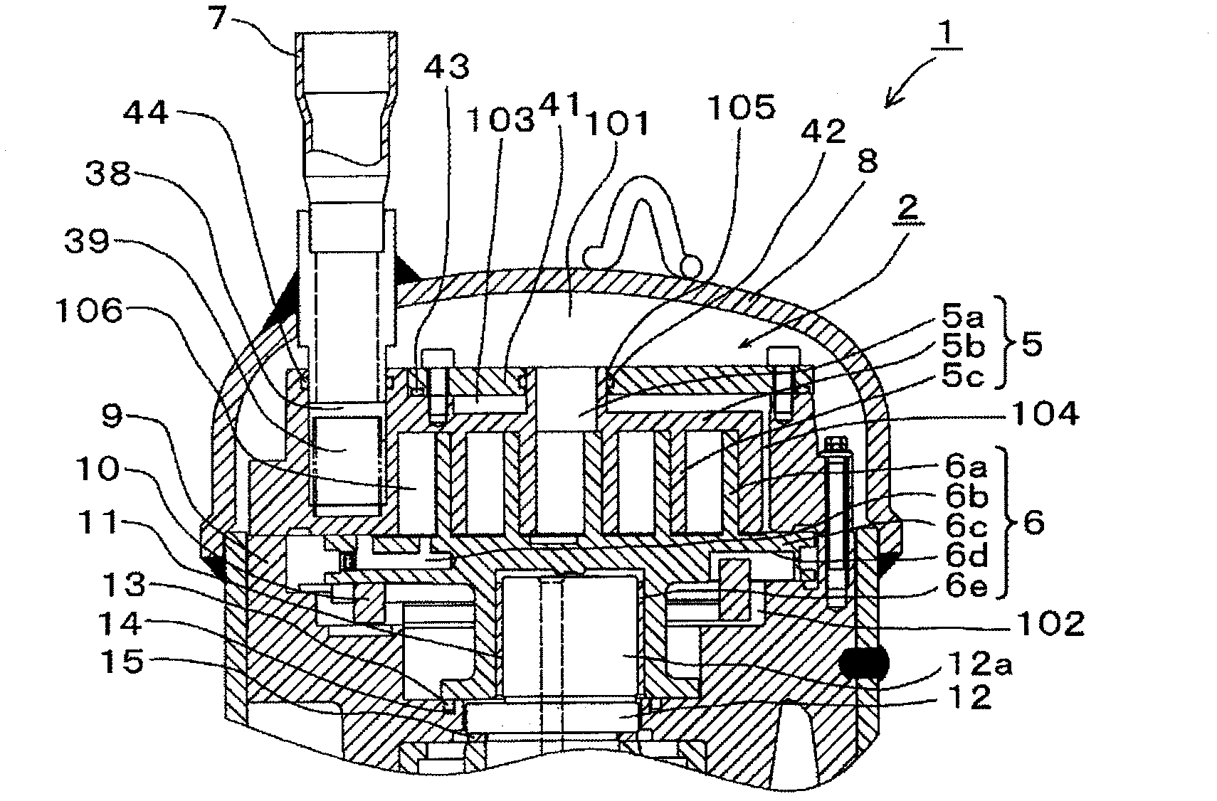
[0072] figure 1 is a longitudinal sectional view of a scroll compressor according to a first embodiment of the present invention, figure 2 yes figure 1 Enlarged view of the compression mechanism.

[0073] The scroll compressor 1 is configured by accommodating a compression mechanism unit 2 , a drive unit 3 , and a rotating shaft 12 in an airtight container 30 . In this embodiment, a vertical scroll compressor in which the compression mechanism part 2 is arranged above and the drive part 3 is arranged below is a so-called high-pressure chamber type compressor.

[0074] The compression mechanism unit 2 is configured with a fixed scroll 5 , an orbiting scroll 6 , and a frame 9 as basic components. The frame 9 is fixed to the airtight container 30 and constitutes a member in which the rolling bearing 16 is arranged. The fixed scroll 5 has a sc...

Embodiment 2

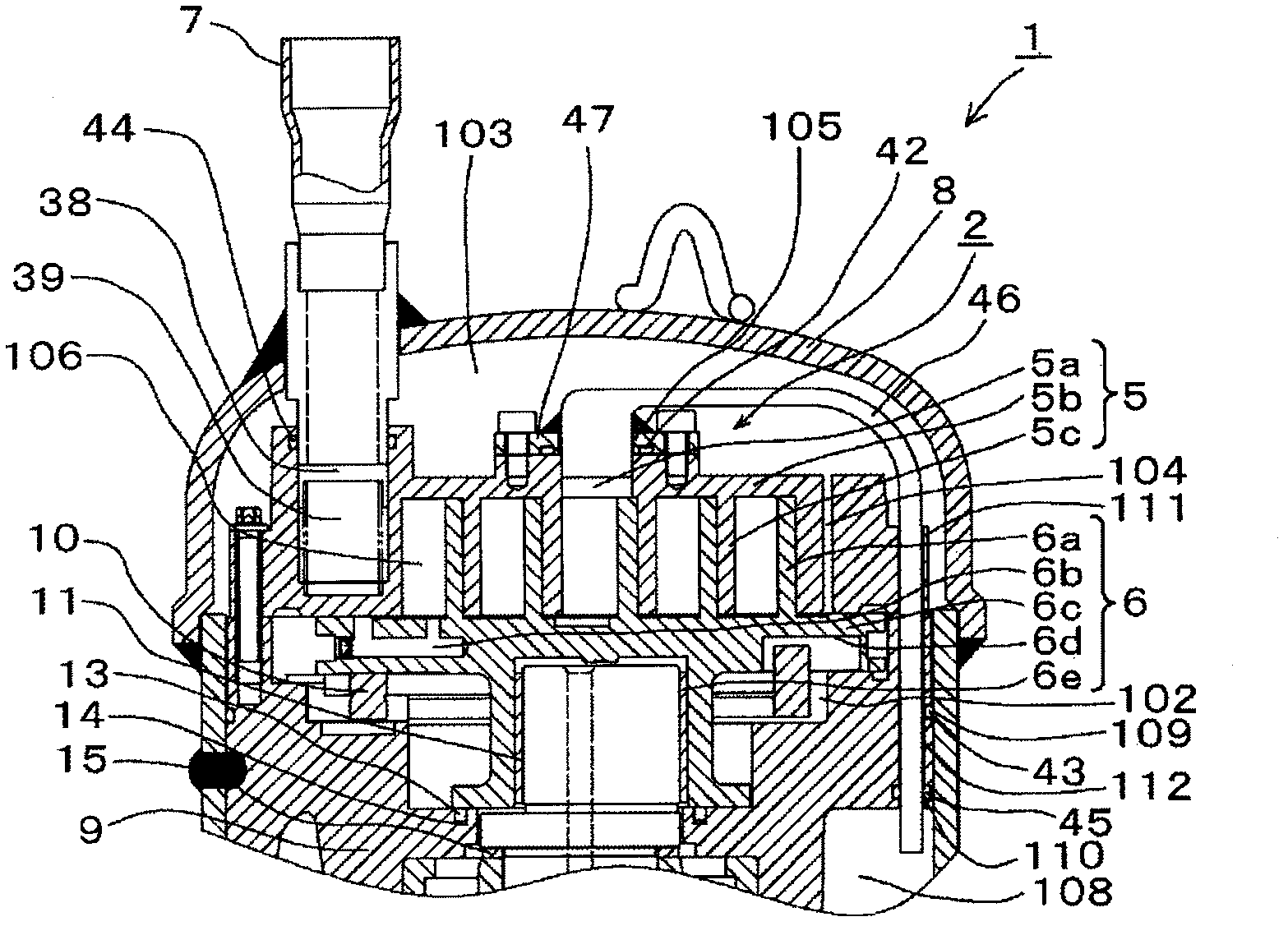
[0096] use image 3 A scroll compressor according to a second embodiment of the present invention will be described.

[0097] Use the space between the fixed scroll top plate 5b and the upper cover 8 as the top plate chamber 103, use the discharge flange 47 to fit one end of the discharge gas guide pipe 46 into the fixed scroll discharge port 5a, and make the discharge gas guide pipe The other end of 46 is guided to the motor upper space 108 through the through holes 111 and 112 provided in the fixed scroll 5 and the frame 9 , so that the fixed scroll discharge port 5 a communicates with the motor upper space 108 . Here, the outer diameter of the frame 9 and the inner wall of the airtight container 30 and the discharge gas guide pipe 46 and the through-hole 112 of the frame 9 are fitted with the sealing members 43 and 45 so that the ceiling chamber 103 does not communicate with the upper space 108 of the motor. combine. Furthermore, the orbiting scroll back pressure chamber ...


PUM


Abstract

Provided is a vortex compressor. In the conventional vortex compressor, the fixed vortex disk top board bears the force generated by the pressure inside an enclosed space (compressing room) formed by two vortex disks at the scroll body side. At the side opposite to the scroll body, the fixed vortex disk top board bears the force generated by the pressure inside an ejecting pressure space. Affected by the combined force, the fixed vortex disk top board is deformed and forms a downward projection shape. On the other hand, the return vortex disk is deformed and forms an upward projection shape affected by the pressure worked on the backside of the return vortex disk. As the deformation may cause the tooth crest and the tooth root at the central section of the scroll body to contact with each other, the conventional vortex compressor increases the sliding loss, leads to the decrease of the performance, and reduces the reliability due to the sintering upon the sliding surface or due to the locking. The utility model aims at providing a vortex compressor featuring high reliability and efficiency. To achieve this objective, the upper portion of the top board of the fixed vortex disk is provided with a top board chamber and a connecting path which communicates the top board chamber with the backpressure chamber.

Description

technical field [0001] The present invention relates to a refrigerant compressor for refrigeration and air conditioning, and a scroll compressor suitable as an air or other gas compressor, and more particularly, to an appropriate scroll compressor capable of achieving high performance and high reliability for various applications. Background technique [0002] The scroll compressor described in Patent Document 1 includes: a discharge pressure space in the center and a pressure (hereinafter referred to as "intermediate pressure") space between the suction pressure and the discharge pressure in the outer peripheral part as the space constituting the orbiting scroll. The space on the back side, and the discharge pressure and intermediate pressure act on the back of the orbiting scroll to press the orbiting scroll to the fixed scroll, so as to prevent the pressure in the closed space formed by the orbiting and fixed scrolls from causing the two scrolls to separate. [0003] In ...

Claims


Application Information

Patent Timeline
IPC IPC(8): F04C18/02
Inventor 深谷美博三宅成志长谷川修士熊仓英之森田惠理太田原优
Owner HITACHI JOHNSON CONTROLS AIR CONDITIONING INC
Why Eureka
Try Eureka