Oil return system for centrifugal cold water unit

A chiller and oil return system technology, applied in refrigerators, refrigeration components, compressors, etc., can solve the problems of oil mixing, poor adaptability, and reduced heat transfer effect of heat exchangers, etc., to achieve stable oil pressure, ideal effect, Oil return stabilization effect

Active Publication Date: 2012-04-04
GREE ELECTRIC APPLIANCES INC
View PDF5 Cites 0 Cited by
  • Summary
  • Abstract
  • Description
  • Claims
  • Application Information

AI Technical Summary

Problems solved by technology

During the operation of the air conditioning unit, oil will be mixed into the refrigerant, which will have two effects. On the one hand, the heat exchange effect of the heat exchanger will be reduced. On the other hand, the oil will continue to be mixed into the refrigerant, and the oil in the oil tank will Less and less, it may cause the unit to fail to operate normally. Therefore, the oil return system in the air conditioning unit is an essential device for the unit
The existing oil return device relies on the high-low pressure difference between the condenser and the evaporator as the injection source. The device is simple, but its adaptability is poor, because the air-conditioning load is constantly changing with the seasons, and the high-low pressure difference between the condenser and the evaporator is also constantly changing. , from theoretical analysis, when the difference between high and low pressure is less than 3bar, effective negative pressure cannot be formed at the nozzle, resulting in poor oil return of the unit, especially when the air conditioner is overloaded. In addition, the oil return system of the existing poor separation

Method used


Image

  • Oil return system for centrifugal cold water unit
  • Oil return system for centrifugal cold water unit

Examples


Embodiment Construction

[0022] Embodiments of the present invention are described in detail below in conjunction with accompanying drawings:

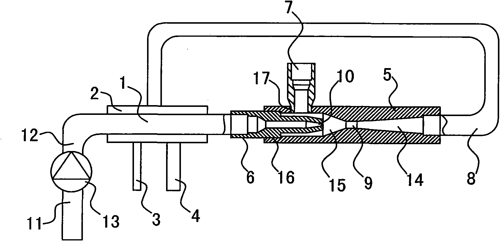
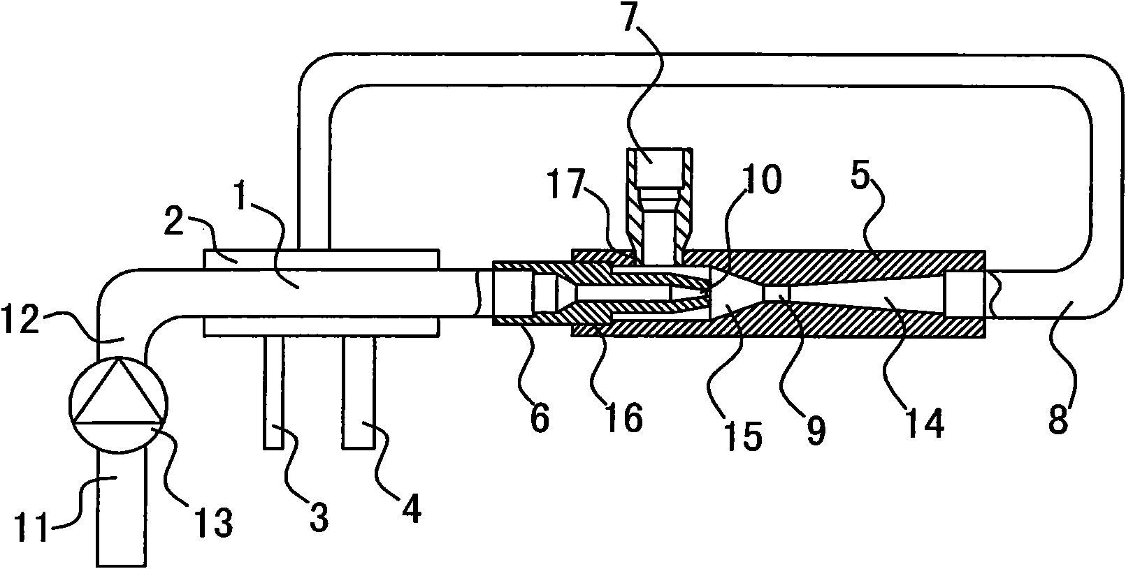
[0023] Such as figure 1 As shown, an oil return system for a centrifugal chiller includes a high-pressure injection source, an oil separation device and an ejector assembly. The oil separation device includes a high-pressure oil pipeline 1, an oil separation pipeline 2, an oil return pipe 3 and an air return pipe 4. A heat exchange structure is formed between the high-pressure oil pipeline 1 and the oil separation pipeline 2. The ejector assembly includes the ejector casing 5, the jet tube 6, the inlet pipe 7, and the outlet pipe 8. Inside the ejector casing 5 A throat 9 is provided, and the high-pressure injection source communicates with the rear end of the jet pipe 6 through the high-pressure oil pipeline 1. The front end of the jet pipe 6 is provided with a nozzle 10, and the nozzle 10 is aligned with the rear end of the throat 9, and the introduction pipe...


PUM


Abstract

The invention discloses an oil return system for a centrifugal cold water unit. The oil return system comprises a high-pressure ejection source, an oil separation device and an ejector component, wherein the oil separation device comprises a high-pressure oil pipeline, an oil separation pipeline, an oil return pipe and an air return pipe; a heat exchange structure is formed between the high-pressure oil pipeline and the oil separation pipeline; the ejector component comprises an ejector shell, a jet pipe, a leading-in pipe and a leading-out pipe; a throat part is arranged in the ejector shell; the high-pressure ejection source is communicated with the rear end of the jet pipe by the high-pressure oil pipeline; a spray nozzle is formed at the front end of the jet pipe and aligns with the rear end of the throat part; the leading-in pipe is communicated with the rear end of the throat part; the front end of the throat part is communicated with the oil separation pipeline by the leading-out pipe; and the oil separation pipeline is communicated with the oil return pipe and the air return pipe. The oil return system has an ideal oil separation effect, and the unit operates stably.

Description

technical field [0001] The invention belongs to the field of air conditioners, and in particular relates to an oil return system for a centrifugal chiller. Background technique [0002] The purpose of using lubricating oil in air conditioning units is mainly to lubricate, cool, seal, disperse stress, prevent rust, etc. During the operation of the air conditioning unit, oil will be mixed into the refrigerant, which will have two effects. On the one hand, the heat exchange effect of the heat exchanger will be reduced. On the other hand, the oil will continue to be mixed into the refrigerant, and the oil in the oil tank will Less and less, it may cause the unit to fail to operate normally. Therefore, the oil return system in the air conditioning unit is an essential device for the unit. The existing oil return device relies on the high-low pressure difference between the condenser and the evaporator as the injection source. The device is simple, but its adaptability is poor, b...

Claims


Application Information

Patent Timeline
Patent Type & Authority Applications(China)
IPC IPC(8): F25B31/00
Inventor 刘华李宏波张治平谢艳群钟瑞兴王晨光王彦川
Owner GREE ELECTRIC APPLIANCES INC
Why Eureka
Try Eureka