
Vacuum transmission process equipment and method

A technology of vacuum transmission and process equipment, which is applied in the direction of conveyor objects, transportation and packaging, and final product manufacturing, which can solve the problems of low production efficiency and achieve high production efficiency

Active Publication Date: 2014-03-05
KINGSTONE SEMICONDUCTOR LIMITED COMPANY
View PDF4 Cites 0 Cited by
  • Summary
  • Abstract
  • Description
  • Claims
  • Application Information

AI Technical Summary

Problems solved by technology

[0004] The technical problem to be solved by the present invention is to overcome the defect of low production efficiency of the vacuum process method in the prior art, and provide a vacuum transmission process equipment with high production efficiency and a corresponding vacuum transmission process method

Method used


Image

  • Vacuum transmission process equipment and method
  • Vacuum transmission process equipment and method
  • Vacuum transmission process equipment and method

Examples


Embodiment 1

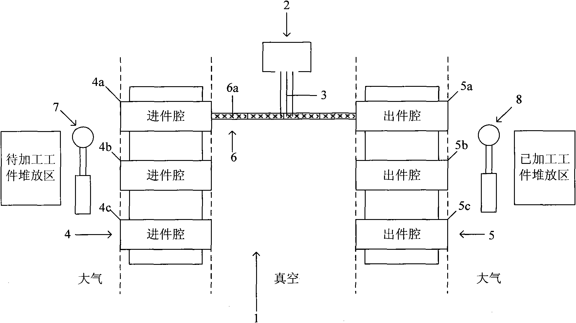
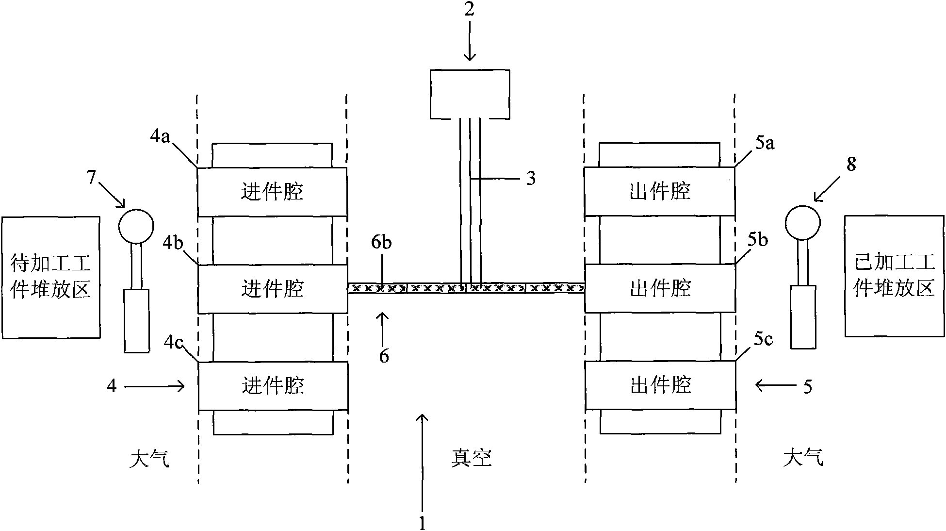
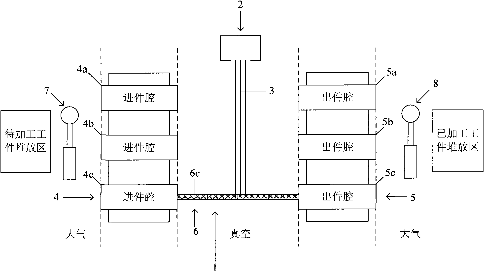
[0020] like Figure 1-3 As shown, the vacuum transmission process equipment of this embodiment first includes a vacuum process chamber 1, and a processing device 2 is arranged in the vacuum process chamber 1, and the processing device 2 uses a processing medium 3 to process the workpiece. The processing device 2 Preferably, the workpiece is processed in a non-contact manner, that is, for example, processing the workpiece with an ion beam or plasma, and at this time the processing medium 3 is correspondingly an ion beam or plasma, and the processing device 2 can also be used for heat treatment or plasma processing of the workpiece. Annealing devices, etc.

[0021] The vacuum transfer process equipment also includes at least two inlet chambers 4 connected to one side of the vacuum process chamber 1, and at least two outlet chambers 5 connected to the other side of the vacuum process chamber 1, each inlet chamber is connected to the other side of the vacuum process chamber 1. Th...

Embodiment 2

[0042] The only difference between the vacuum transmission process equipment in this embodiment and the vacuum transmission process equipment in Embodiment 1 is that in Embodiment 1, the inlet cavity 4-vacuum process cavity 1-outlet cavity 5 forms a linear route, and the transmission Platform 6 reciprocates along this linear route; And in embodiment 2, as Figure 4 As shown, the entry chamber 4->vacuum process chamber 1->outlet chamber 5->atmospheric environment forms a circular route, and the transmission platform 6 is along the Figure 4 The direction indicated by the arrow in the center moves in one direction along the circular route; in addition, since the workpiece loading and workpiece unloading actions for each inlet cavity and outlet cavity can be performed in the same area in the atmospheric environment at this time, so Correspondingly, in Embodiment 2, there is no need to set up two mechanical arms, but only one first mechanical arm 7 needs to be set. It is responsi...


PUM


Abstract

The invention discloses a piece of vacuum transmission process equipment, which comprises at least two workpiece inlet cavity, at least two workpiece outlet cavities, at least two transmission platforms, a first mechanical arm and a second mechanical arm, wherein the processing medium can pass through each transmission platform but cannot pass through the workpieces; each transmission platform is used for in turn continuously transmitting the workpieces from the workpiece inlet cavity to the workpiece outlet cavity through the vacuum process cavity after loading the workpieces; the workpieces are continuously processed by the processing medium on different planes; and the workpieces are transmitted from the workpiece outlet cavity to the workpiece inlet cavity after being unloaded. The invention also discloses another piece of vacuum transmission process equipment and two vacuum transmission process methods. The whole process can be ensured to be continuously and effectively carried out, thereby realizing very high production efficiency.

Description

technical field [0001] The invention relates to vacuum process technology, in particular to a vacuum transmission process equipment and a corresponding vacuum transmission process method. Background technique [0002] New energy is one of the five most decisive technological fields in the world's economic development in the 21st century, and solar energy is a clean, efficient and inexhaustible new energy. In the new century, governments of all countries regard the utilization of solar energy resources as an important content of the national sustainable development strategy. Photovoltaic power generation has many advantages such as safety, reliability, no noise, no pollution, less constraints, low failure rate, and easy maintenance. In recent years, with the rapid development of the international photovoltaic power generation industry, the supply of solar wafers exceeds the demand, so improving the photoelectric conversion efficiency of solar wafers and the production capacit...

Claims


Application Information

Patent Timeline
Patent Type & Authority Patents(China)
IPC IPC(8): H01L21/67H01L21/677H01L31/18
CPCY02P70/50
Inventor 陈炯钱锋
Owner KINGSTONE SEMICONDUCTOR LIMITED COMPANY
Learn More