
Ion implantation system and methods

An ion implantation system and ion implantation technology, applied in the field of solar wafer manufacturing, can solve the problems of inability to achieve optimal production efficiency, inconvenient control and power supply design, and high cost, so as to improve photoelectric conversion efficiency, improve use safety, and reduce equipment costs. cost effect

Active Publication Date: 2014-07-09
KINGSTONE SEMICONDUCTOR LIMITED COMPANY
View PDF6 Cites 0 Cited by
  • Summary
  • Abstract
  • Description
  • Claims
  • Application Information

AI Technical Summary

Problems solved by technology

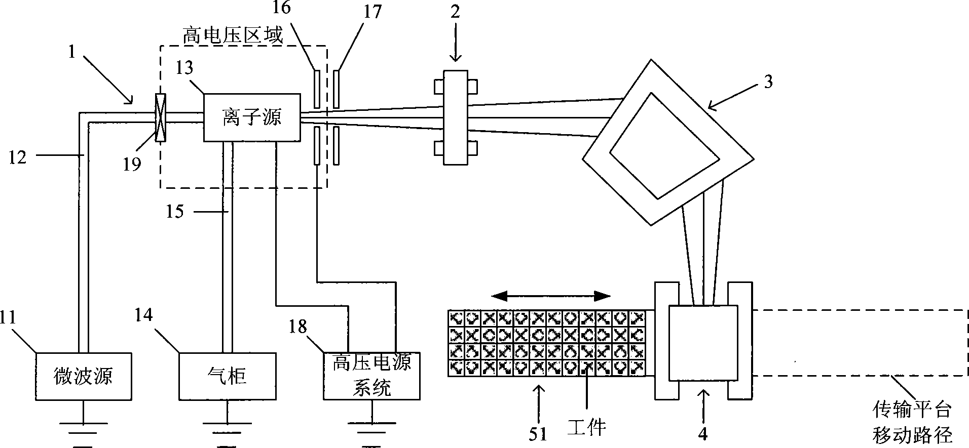
[0006] The technical problem to be solved by the present invention is to overcome the disadvantages of inconvenient control and power supply design, high cost, and inability to achieve optimal production efficiency of the ion implantation system in the prior art because the ion source system as a whole works under high voltage. Provide an ion implantation system and a corresponding ion implantation method that enable the ion source system to work without the overall operation under high voltage and can achieve optimal production efficiency

Method used


Image

  • Ion implantation system and methods
  • Ion implantation system and methods
  • Ion implantation system and methods

Examples


Embodiment 1

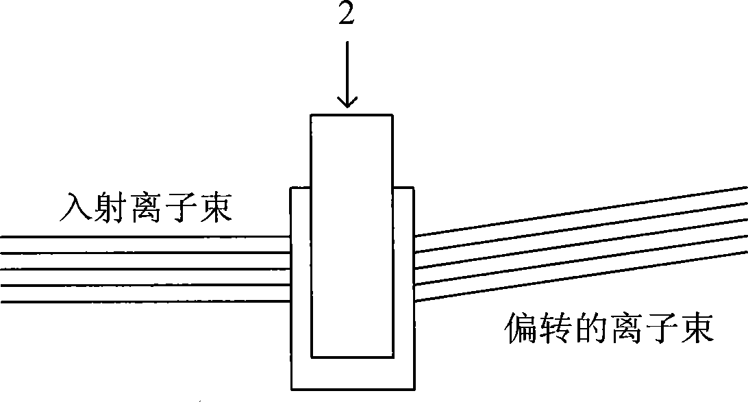
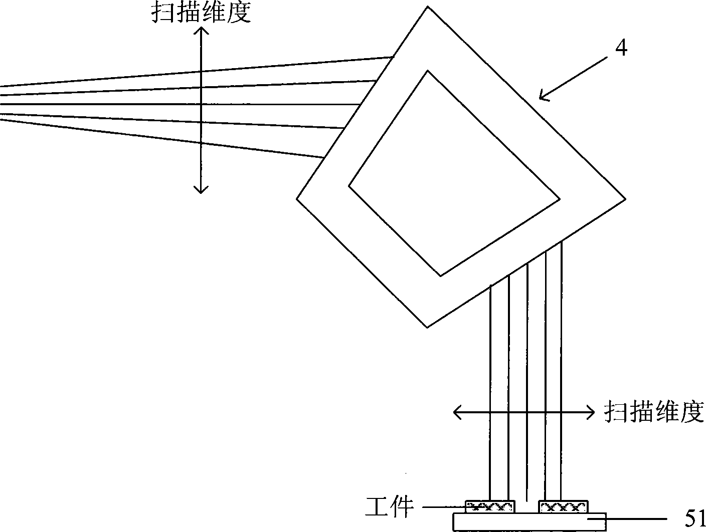
[0054] refer to figure 1 and Figure 6 As shown, the ion implantation system of the present invention first includes an ion source system 1 for generating an ion beam, and the ion beam is transported in a vacuum chamber 6 . On the transmission path of the ion beam, there are successively: a scanning magnet 2, such as figure 2 shown, the scanning magnet 2 will be in the figure 2 The ion beam passing through is continuously scanned up and down within the dimension of the paper, so that the ion beam has a certain angular distribution in the scanned dimension. figure 2 At the moment shown, the scanning magnet 2 is deflecting the passing ion beam upward in the paper dimension, and the scanned dimension of the ion beam is hereinafter referred to as the scanning dimension, figure 1 Before the ion beam arrives at a calibration magnet 4 that will be mentioned below, its scanning dimension is all perpendicular to the paper surface; a mass analysis magnet 3, which makes the ion bea...

Embodiment 2

[0058] The front view of the ion implantation system in this embodiment is as follows Figure 4 As shown, the only difference between this ion implantation system and Embodiment 1 is: firstly, the correction magnet 4 is omitted in this embodiment; secondly, it is assumed that the transmission platform 51 is guaranteed to carry the workpiece and move horizontally as in Embodiment 1 , then the arrangement directions of the ion source system 1, the scanning magnet 2, and the mass analysis magnet 3 in the ion implantation system of this embodiment will differ from those in Embodiment 1 by 90°, but their structures remain the same Change.

[0059] Owing to the omission of the entire magnet system of the calibration magnet 4, not only can the reliability of the entire ion implantation system be significantly improved, but also the length of the ion beam transmission path can be greatly shortened, thus making the design of the beam transmission part simpler.

[0060] but if Figure...


PUM


Abstract

The invention discloses an ion implantation system which comprises an ion source system, a scanning magnet, a quality analysis magnet and work piece transmission equipment; the ion source system comprises a microwave source which is arranged at ground potential, a gas holder which is arranged at the ground potential, a cooling water system which is arranged at the ground potential, an ion beam extraction system which is arranged in front of the head of an ion source and a high-voltage power system which is arranged at the ground potential; the microwave source is connected with the ion source through a waveguide, and a high-voltage isolation device is arranged on the waveguide; the gas holder is connected with the ion source through an intake pipe; the cooling water system is connected with the head of the ion source and is used for cooling the head of the ion source; the ion beam extraction system comprises a suppression electrode and a ground electrode; and the high-voltage power system is used for supplying power to the head of the ion source and the suppression electrode. The invention also discloses two ion injection methods. According to the invention, the ion source system does not need to work at high voltage in an overall way, and the optimal production efficiency can be realized.

Description

technical field [0001] The invention relates to the field of solar wafer manufacturing, in particular to an ion implantation system and a corresponding ion implantation method. Background technique [0002] New energy is one of the five most decisive technological fields in the world's economic development in the 21st century, and solar energy is a clean, efficient and inexhaustible new energy. In the new century, governments of all countries regard the utilization of solar energy resources as an important content of the national sustainable development strategy. Photovoltaic power generation has many advantages such as safety, reliability, no noise, no pollution, less constraints, low failure rate, and easy maintenance. In recent years, with the rapid development of the international photovoltaic power generation industry, the supply of solar wafers exceeds the demand, so improving the photoelectric conversion efficiency of solar wafers and the production capacity of solar ...

Claims


Application Information

Patent Timeline
Patent Type & Authority Patents(China)
IPC IPC(8): H01J37/317
Inventor 陈炯钱锋
Owner KINGSTONE SEMICONDUCTOR LIMITED COMPANY
Learn More