Device and method for monitoring a hadron beam

一种强子束、设备的技术,应用在强子治疗领域

Active Publication Date: 2012-04-04
ION BEAM APPL
View PDF7 Cites 7 Cited by
  • Summary
  • Abstract
  • Description
  • Claims
  • Application Information

AI Technical Summary

Problems solved by technology

The main disadvantage of this device is the need to apply geometric corrections to make the beam range values ​​measured by the MLIC correspond to the actual beam range traversed in water
This drawback is especially acute when measuring hadron therapy beams delivered with known energy modulation techniques in which the SAD (source-to-axis distance) varies

Method used


Image

  • Device and method for monitoring a hadron beam
  • Device and method for monitoring a hadron beam
  • Device and method for monitoring a hadron beam

Examples


Embodiment Construction

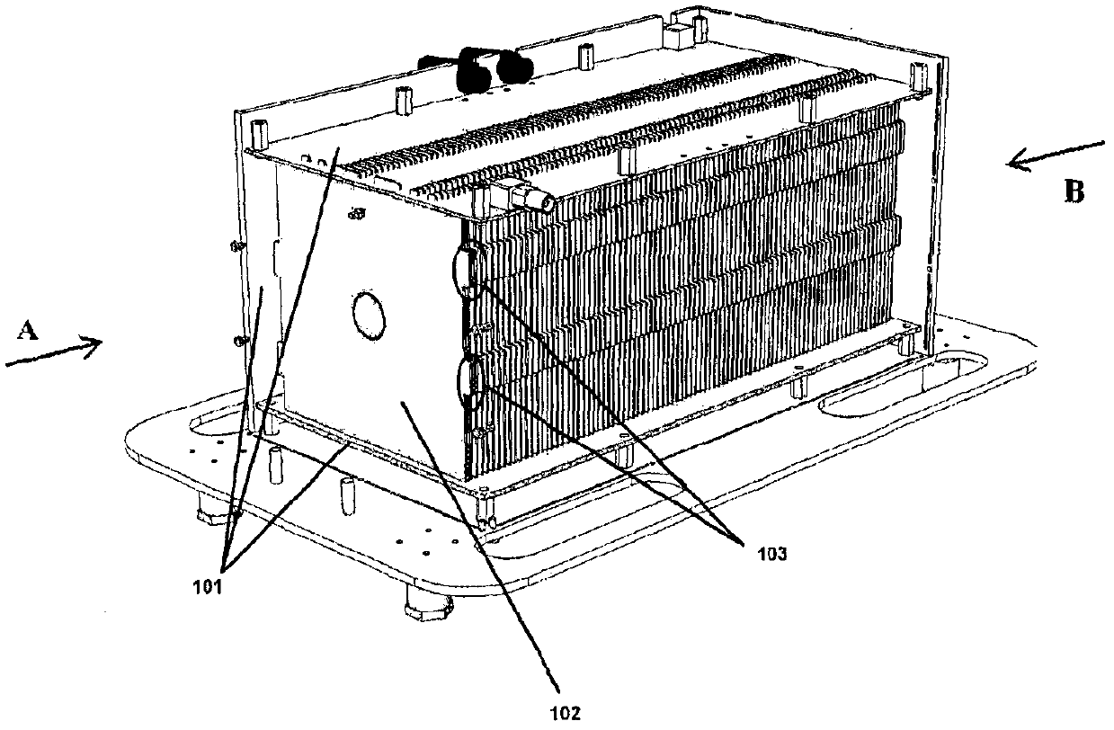
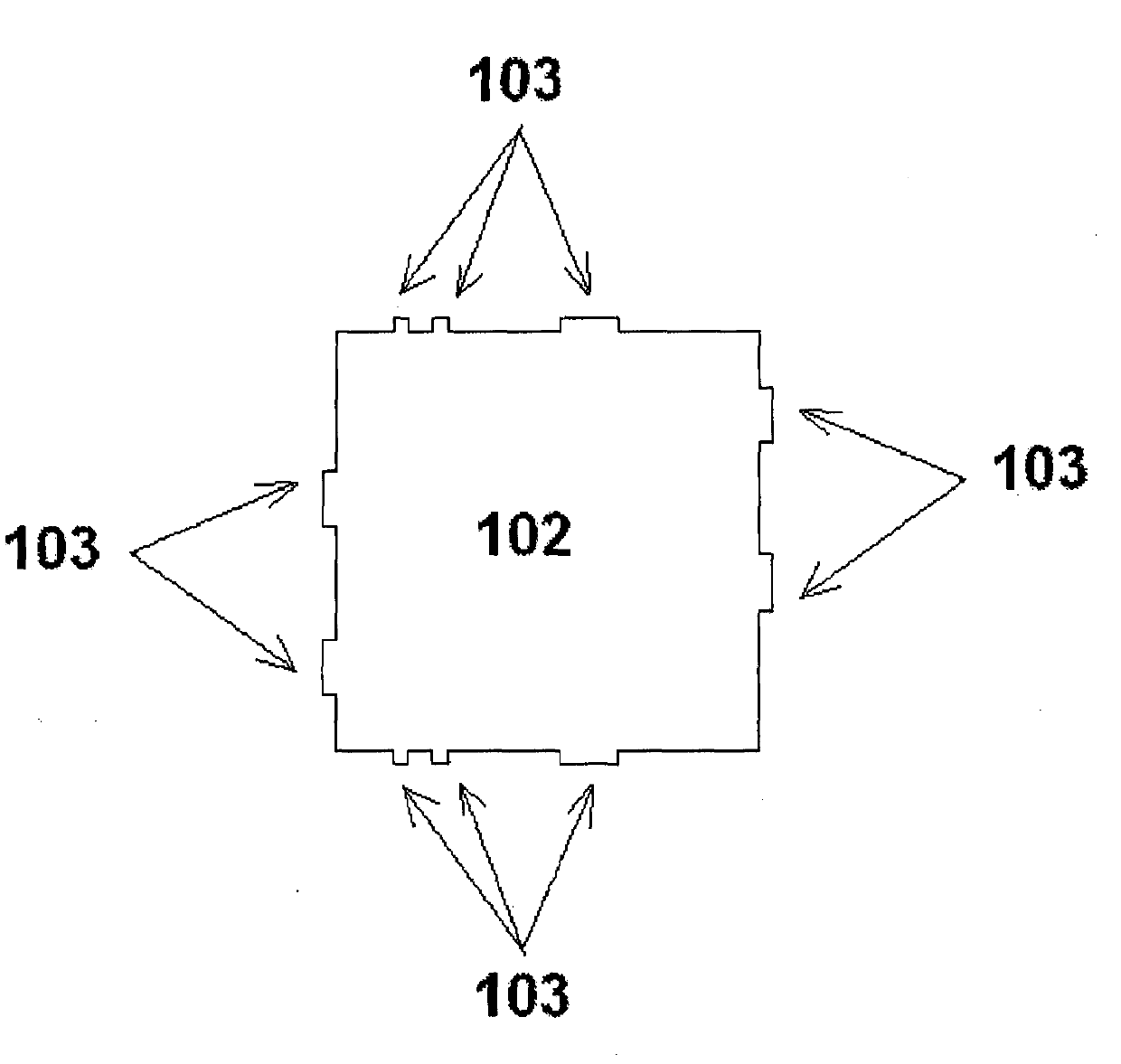
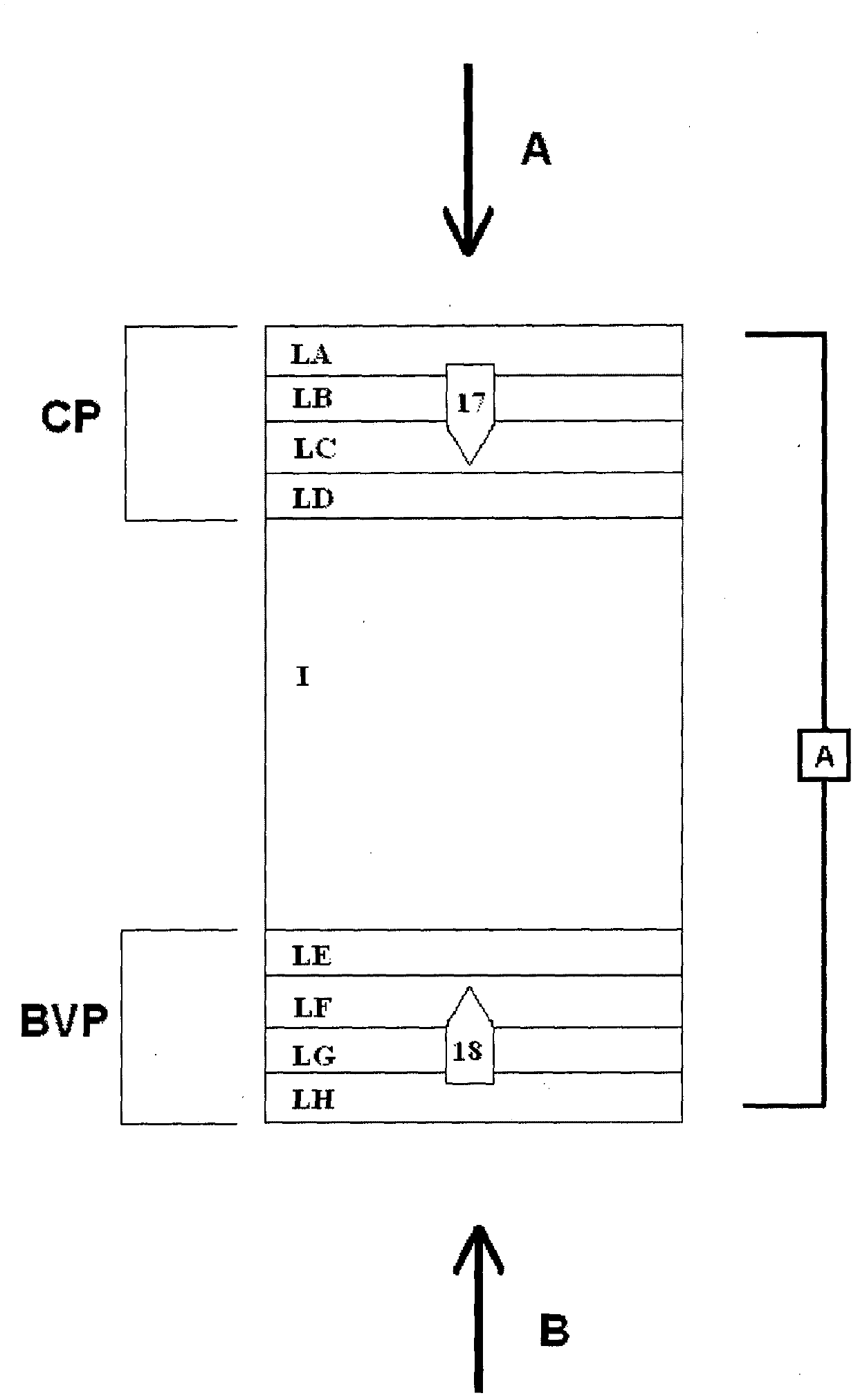
[0072] In a first aspect, the invention relates to a device for dosimetric monitoring of hadron beams, comprising n consecutive Each detector plate has a collection portion comprising a collection side insulated from a bias portion comprising a bias side, and in such a way that said collection side faces said bias side of a subsequent detector plate or vice versa Arranged in a way, each detector board includes m material layers L k , the resulting assembly of these detector plates forms a plurality of ionization chamber units, characterized by:

[0073] Each layer L constituting each detector board k thickness l k and the choice of material and the gap of ion chamber unit i have been selected to satisfy the following formula for each ion chamber i:

[0074] l gi = [ Σ k = 1 m ...


PUM


Abstract

The present invention relates to a device for dosimetry monitoring of a hadron beam, comprising n successive ionization chambers i obtained by a series or stack of n+1 parallel detector plates separated from each other by a gas filled gap, each detector plates having a collecting part comprising a collecting side insulated from a bias voltage part comprising a bias voltage side and arranged in a such way that the said collecting side is facing the said bias voltage side of a subsequent detector plate or inversely, each detector plate comprising m layers Lk of materials, the resulting assembly of these detector plates forming a plurality of ionization chamber cells, characterised in that: the thicknesses lk and the choice of the materials of each layer Lk constituting each detector plate as well as the gap of an ionization chamber cell i have been selected in order to satisfy the equation (I) for each ionization chamber i, where lgi is the gas filled gap distance between two detector plates; Ik is the thickness of the corresponding layer Lk of a detector plate and; WETk is the water equivalent thickness (WET) o f the corresponding layer Lk of a detector plate.

Description

technical field [0001] The present invention relates to the field of hadron therapy, ie radiation therapy using strongly interacting particles. More specifically, the present invention relates to devices and methods for monitoring hadron beams. Background technique [0002] Currently, it is known that hadrons (ie, neutrons, protons, muons, ions, such as carbon ions) have a physical advantage over X-rays or gamma rays in the field of radiotherapy. Hadrons, especially protons of a given energy (ie form a monoenergetic beam), have a defined range and do not penetrate beyond that range. Furthermore, they deposit their maximum radiation energy value in the so-called Bragg Peak which corresponds to the point of maximum radiation penetration as eg a tumor in the target volume to be treated. Since the position of the Bragg peak depends on the energy of the hadron beam, it is clear that by precisely controlling and modifying this energy, the Bragg peak can be placed at the correspo...

Claims


Application Information

Patent Timeline
Patent Type & Authority Applications(China)
IPC IPC(8): G01T1/29
CPCG01T1/2935
Inventor B·马尔昌德C·布鲁萨斯科S·德·纽特F·弗列德尔
Owner ION BEAM APPL
Why Eureka
Try Eureka