Plasma accelerator with closed electron drift

a technology of electron drift and accelerator, which is applied in the field of closed electron drift of plasma accelerators, can solve the problems of limited application, inability to use as an engine in space, and inability to achieve the degree of ionization of active gas in the stilling zone, and achieve the effect of improving efficiency

Active Publication Date: 2005-02-17
SN DETUDE & DE CONSTR DE MOTEURS DAVIATION S N E C M A
View PDF11 Cites 31 Cited by
  • Summary
  • Abstract
  • Description
  • Claims
  • Application Information

AI Technical Summary

Benefits of technology

An object of the invention is to remedy the drawback of prior art plasma accelerators...

Problems solved by technology

Such ion sources operate in the low current density range (ji<2 milliamps per square centimeter (mA/cm2)) and they are effective only with high acceleration voltages (U>1000 volts (V)), which limits their applications.
That is why, at pre...

Method used


Image

  • Plasma accelerator with closed electron drift
  • Plasma accelerator with closed electron drift
  • Plasma accelerator with closed electron drift

Examples


Embodiment Construction

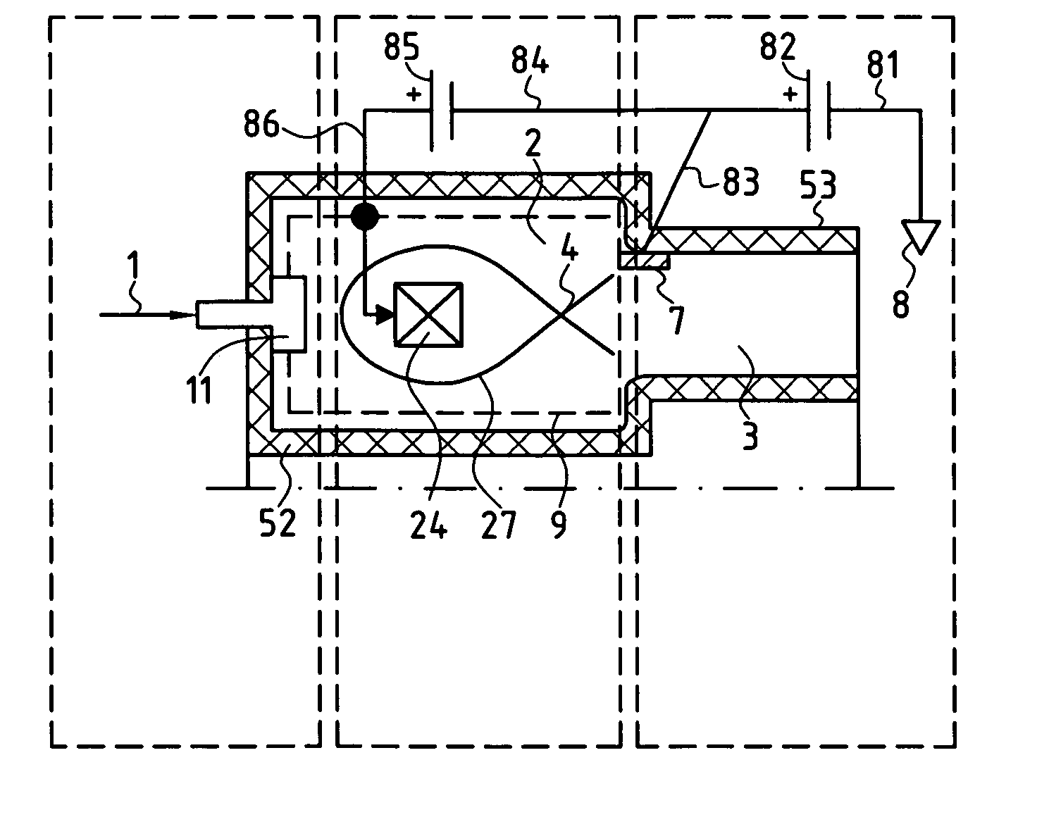
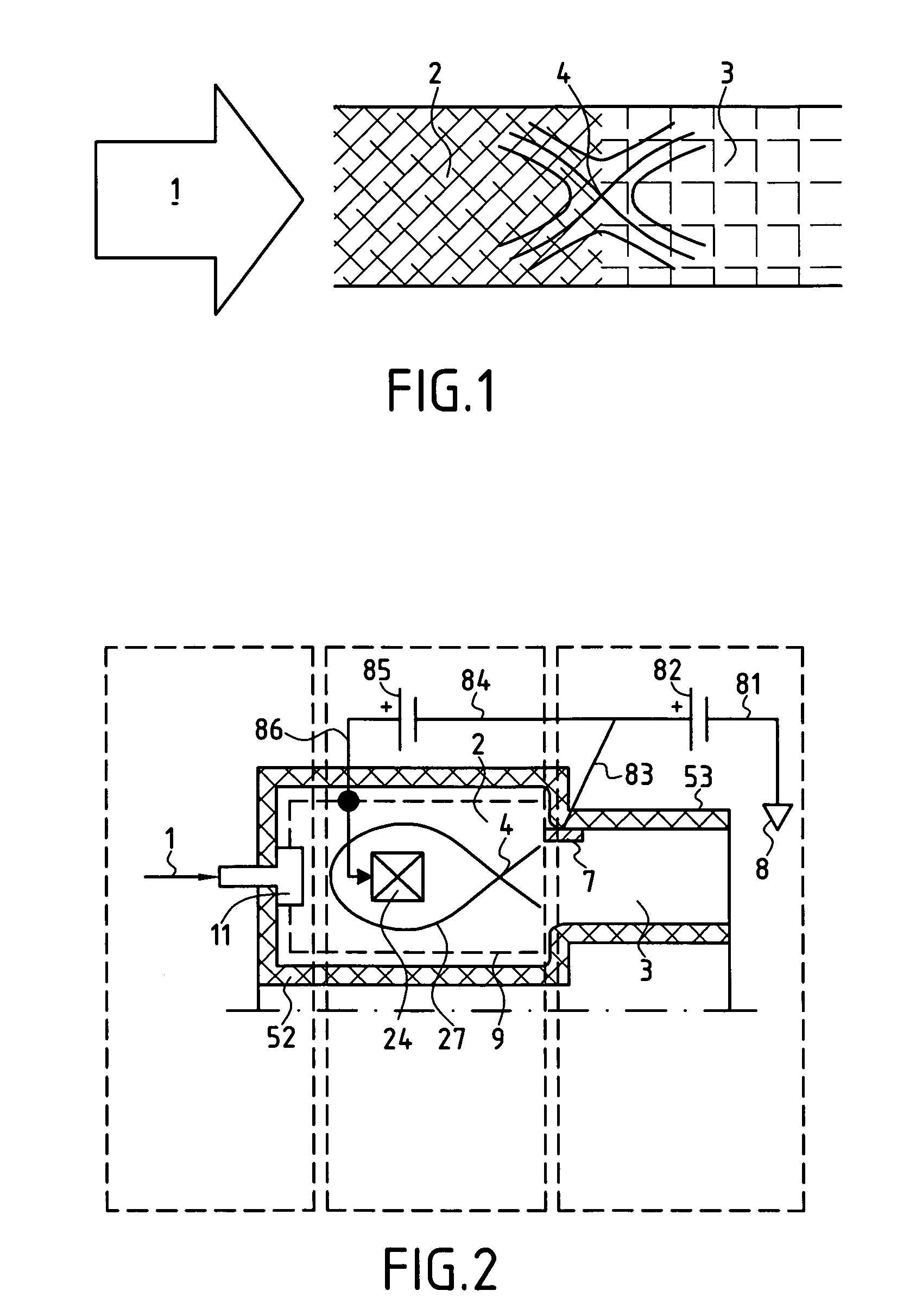
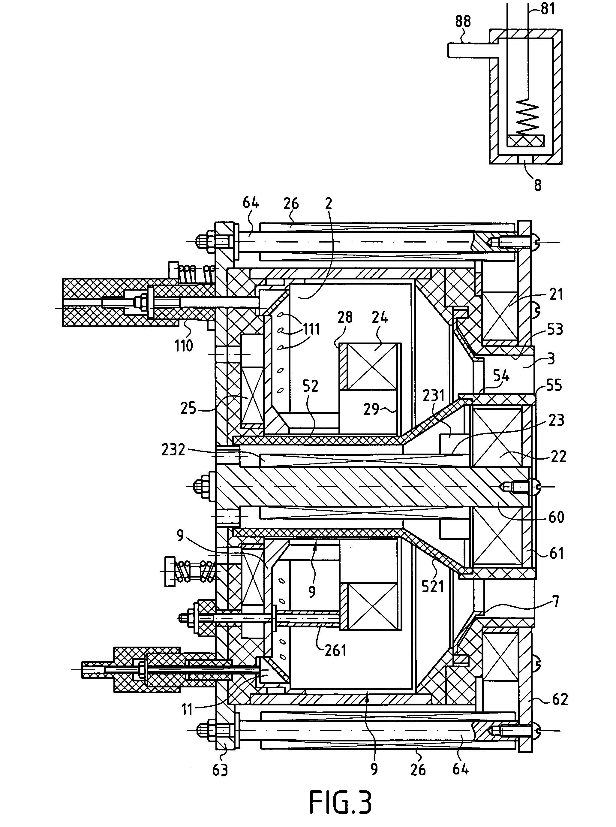
FIG. 3 shows an example of a plasma accelerator in accordance with the invention.

Such a closed electron drift plasma accelerator comprises a first chamber 2 defined by walls 52 made of electrically-insulating material having inside faces covered in a conductive material 9. This first chamber 2 constitutes an ionizing chamber or stilling chamber.

A second chamber 3 referred to as an acceleration chamber comprises an annular acceleration channel 53 of electrically-insulating material with an outlet 55 that is open in the downstream direction. The upstream portion 54 of the acceleration channel 53 communicates with the cavity of the ionization chamber 2 which lies on the same axis as the acceleration chamber 3.

A hollow gas discharge cathode 8 is located outside the acceleration channel 53 in the vicinity of its outlet 55. Reference 81 designates the line electrically connecting the cathode to the negative pole of a first direct current (DC) voltage source 82 (FIG. 2). Reference 88 ...


PUM


Abstract

The closed electron drift plasma accelerator comprises an annular ionization chamber, an acceleration chamber on the same axis as the ionization chamber, an annular anode, a hollow cathode, a first DC voltage source, an annular gas manifold, a magnetic circuit, and magnetic field generators. A coaxial annular coil is placed in the cavity of the ionization chamber, is provided with bias conductive cladding connected, together with the electrically-conductive material of the inside faces of the walls of the ionization chamber, to the positive pole of a second voltage source whose negative pole is connected to the anode, and constitutes an additional magnetic field generator which, together with the other magnetic field generators, forms a magnetic field having a magnetic line of force with an “X” point corresponding to a magnetic field zero situated between the coaxial annular coil and the anode.

Description

FIELD OF THE INVENTION The present invention relates to plasma accelerators with closed electron drift, which accelerators constitute plasma ion sources that can be used in particular as steady plasma thrusters in space, and also in other technical fields, for example in treating mechanical parts with ions. PRIOR ART Ion sources are already known that are constituted by two-stage systems serving to perform electrostatic acceleration of the ion flux. An example of such an ion source is described in patent document WO 01 / 93293. In that document, an ion source comprises a cathode chamber with a gas manifold, while a hollow anode forms an anode chamber connected to the cathode chamber via the outlet orifice that is formed through the wall thereof. An electrostatic system serves to extract ions with the electrically-insulated emission electrode placed in the outlet orifice of the cathode chamber. A magnetic system establishes a magnetic field in the cathode and anode chambers, the fie...

Claims


Application Information

Patent Timeline
IPC IPC(8): H05H1/24H05H1/54
CPCH05H1/54F03H1/0075
Inventor SECHERESSE, OLIVIERBOUGROVA, ANTONINAMOROZOV, ALEXEI
Owner SN DETUDE & DE CONSTR DE MOTEURS DAVIATION S N E C M A
Why Eureka
Try Eureka