Decaborane ion source

Inactive Publication Date: 2005-10-25
AXCELIS TECHNOLOGIES
View PDF5 Cites 32 Cited by
  • Summary
  • Abstract
  • Description
  • Claims
  • Application Information

AI Technical Summary

Benefits of technology

[0015]The ionizer comprises a body having an inlet for receiving the vaporized decaborane; an ionization chamber in which the vaporized decaborane may be ionized by an energy-emitting element to create a plasma; and an exit aperture for extracting an ion beam comprised of the plasma. A cooling mechanism is provided for lowering the temperature of walls of the ionization chamber (e.g.,

Problems solved by technology

In low energy applications, however, the beam of boron ions will suffer from a condition known as “beam blow-up”, which refers to the tendency for like-charged ions within the ion beam to mutually repel each other.
This severely reduces beam transmission as beam energy is reduced.
However, decaborane ion sources to date have been unsuccessful at generating sufficient ion beam current for production applications of boron implants.
Known hot-cathode sources are unsuitable for decaborane ionization

Method used


Image

  • Decaborane ion source
  • Decaborane ion source
  • Decaborane ion source

Examples


Embodiment Construction

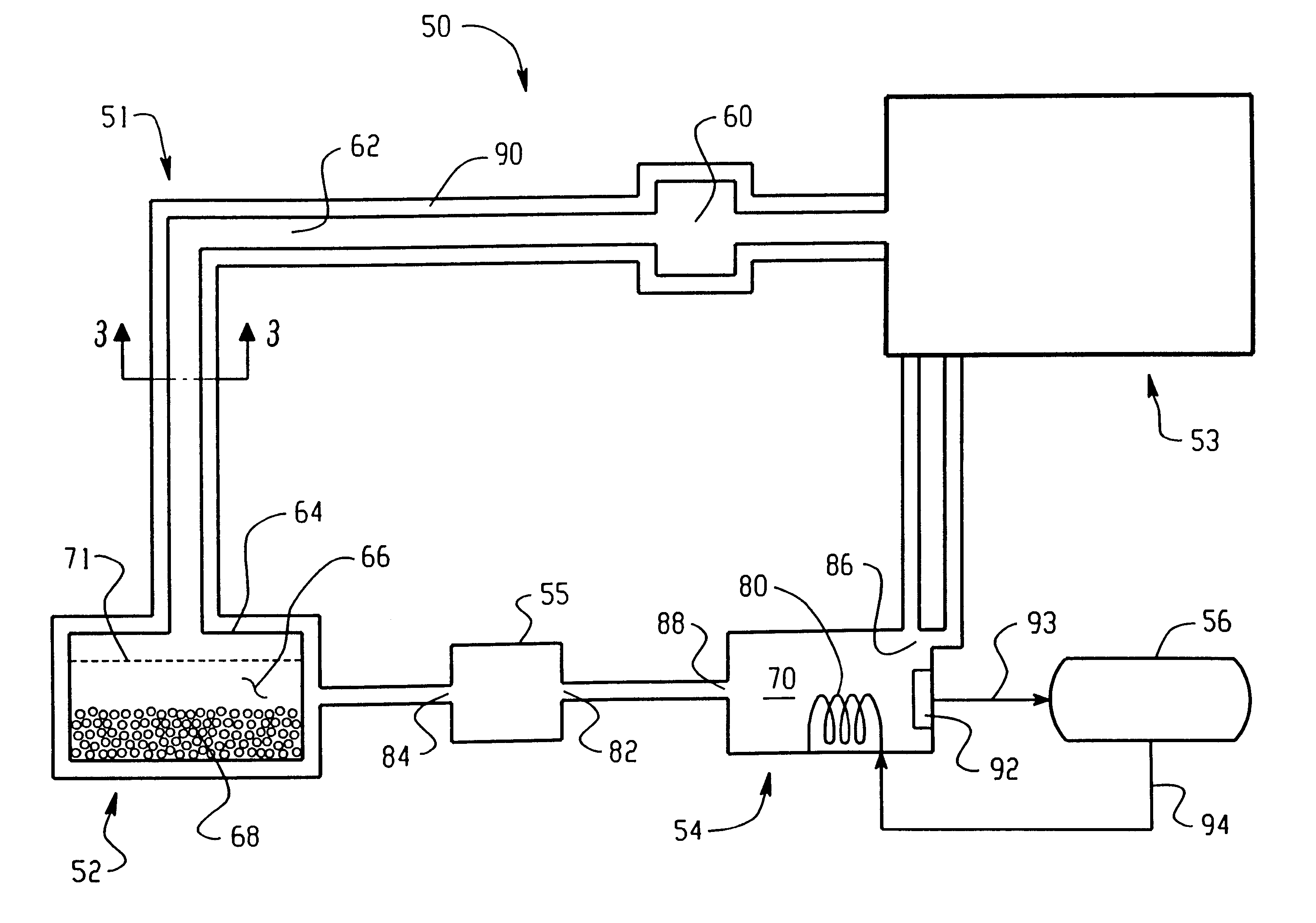
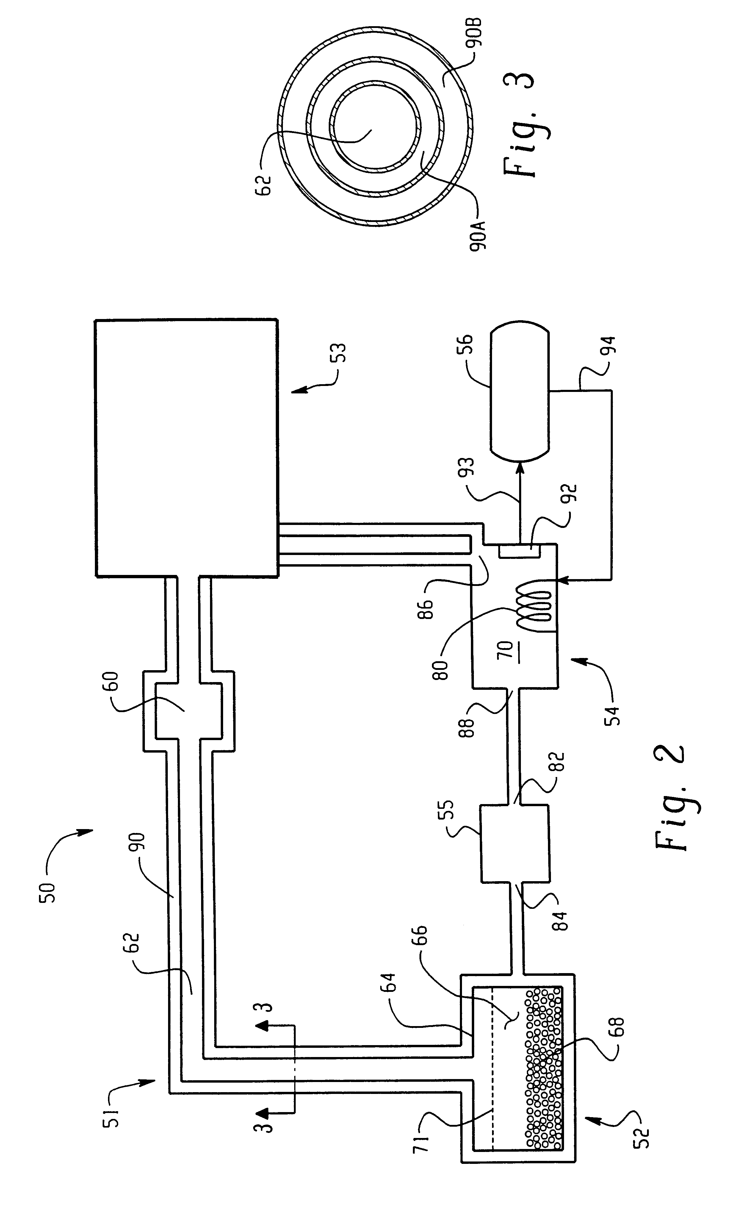
[0020]Referring now to FIGS. 2-4 of the drawings, and initially to FIG. 2, an ion source 50 comprising a vaporizer 51 and an ionizer 53 are shown, constructed according to the present invention. The vaporizer 51 comprises a non-reactive, thermally conductive sublimator or crucible 52, a heating medium reservoir 54, a heating medium pump 55, a temperature controller 56, and a mass flow controller 60. Ionizer 53 is shown in more detail in FIG. 3. The crucible 52 is located remotely from the ionizer 53 and connected thereto by a feed tube 62, constructed of quartz or stainless steel. In the disclosed embodiment, the feed tube 62 is surrounded by an outer single-chamber annular sheath 90 along substantially the entire length thereof.

[0021]The crucible 52 provides a container 64 enclosing a cavity 66 for containing a source material 68. The container is preferably made of a suitable non-reactive (inert) material such as stainless steel, graphite, quartz or boron nitride and which is capa...


PUM


Abstract

An ion source (50) for an ion implanter is provided, comprising a remotely located vaporizer (51) and an ionizer (53) connected to the vaporizer by a feed tube (62). The vaporizer comprises a sublimator (52) for receiving a solid source material such as decaborane and sublimating (vaporizing) the decaborane. A heating mechanism is provided for heating the sublimator, and the feed tube connecting the sublimator to the ionizer, to maintain a suitable temperature for the vaporized decaborane. The ionizer (53) comprises a body (96) having an inlet (119) for receiving the vaporized decaborane; an ionization chamber (108) in which the vaporized decaborane may be ionized by an energy-emitting element (110) to create a plasma; and an exit aperture (126) for extracting an ion beam comprised of the plasma. A cooling mechanism (100, 104) is provided for lowering the temperature of walls (128) of the ionization chamber (108) (e.g., to below 350° C.) during ionization of the vaporized decaborane to prevent dissociation of vaporized decaborane molecules into atomic boron ions. In addition, the energy-emitting element is operated at a sufficiently low power level to minimize plasma density within the ionization chamber (108) to prevent additional dissociation of the vaporized decaborane molecules by the plasma itself.

Description

RELATED APPLICATION[0001]This application is a divisional patent application of Ser. No. 09 / 416,159 filed on Oct. 11, 1999 now U.S. Pat. No. 6,288,403. The contents of all of the aforementioned application(s) are hereby incorporated by reference.[0002]The following U.S. patent application, commonly assigned to the assignee of the present invention, is incorporated by reference herein as if it had been fully set forth: application Ser. No. 09 / 070,685, filed Apr. 30, 1998, and entitled DECABORANE VAPORIZER.FIELD OF THE INVENTION[0003]The present invention relates generally to ion sources for ion implantation equipment and more specifically to an ion source for ionizing decaborane.BACKGROUND OF THE INVENTION[0004]Ion implantation has become a standard accepted technology of industry to dope workpieces such as silicon wafers or glass substrates with impurities in the large scale manufacture of items such as integrated circuits and flat panel displays. Conventional ion implantation syste...

Claims


Application Information

Patent Timeline
IPC IPC(8): H01J27/08H01J27/02H01J37/30H01J27/16H01J37/08H01J37/317
CPCH01J27/08H01J37/30
Inventor HORSKY, THOMAS N.PEREL, ALEXANDER S.LOIZIDES, WILLIAM K.
Owner AXCELIS TECHNOLOGIES
Why Eureka
Try Eureka