Carbon nanotube electron ionization sources

a carbon nanotube and electron ionization technology, applied in the direction of instruments, particle separator tube details, separation processes, etc., can solve the problems of affecting the electron work function of the filament, affecting the lifetime of the filament, and affecting the electron work function

Active Publication Date: 2005-04-26
THERMO ELECTRON A DE
View PDF8 Cites 32 Cited by
  • Summary
  • Abstract
  • Description
  • Claims
  • Application Information

AI Technical Summary

Benefits of technology

[0013]One aspect of the invention relates to ion sources for use in a mass spectrometer. An ion source in accordance with aspects of the invention includes an electron emitter assembly configured to emit electron beams, wherein the electron emitter assembly comprises carbon nanotube bundles fixed to a substrate for emitting the electron beams, a first control grid configured to control emission of the electron beams, and a second control grid configured to control energies of the electron beams; an ionization chamber having an electron-beam inlet to allow the electron beams to enter the ionization chamber, a sample inlet for sample introduction, and an ion-beam outlet to provide an exit for ionized sample molecules; an electron lens disposed between the electron emitter assembly and the ionization chamber to focus the electron beams; and at least one electrode disposed proximate the ion-beam outlet to focus the ionized sample molecules exiting the ionization chamber.

Problems solved by technology

Interactions between the sample gas and the hot filament may result in changes in the electron work function of the filament.
There are several problems associated with the filament assemblies used in electron impact or chemical ionization source.
The primary problem is that the origin and trajectory of the electrons are ill defined.
Additionally, the electron emission relies on the vaporization of material, which results in a limited filament lifetime.
Interactions between the sample gas and the hot filament may result in changes in the electron work function of the filament.
However, regulation of the trap current will alter filament temperature.
This can lead to fluctuation in the temperature distribution in the ion source and cause the assembly to become misaligned.
As a result, it is often difficult, if not impossible, to de-convolute a mass spectrum of a complex mixture sample, due to inevitable uncertainties in the contributions from the components in the mixture.

Method used


Image

  • Carbon nanotube electron ionization sources
  • Carbon nanotube electron ionization sources
  • Carbon nanotube electron ionization sources

Examples


Embodiment Construction

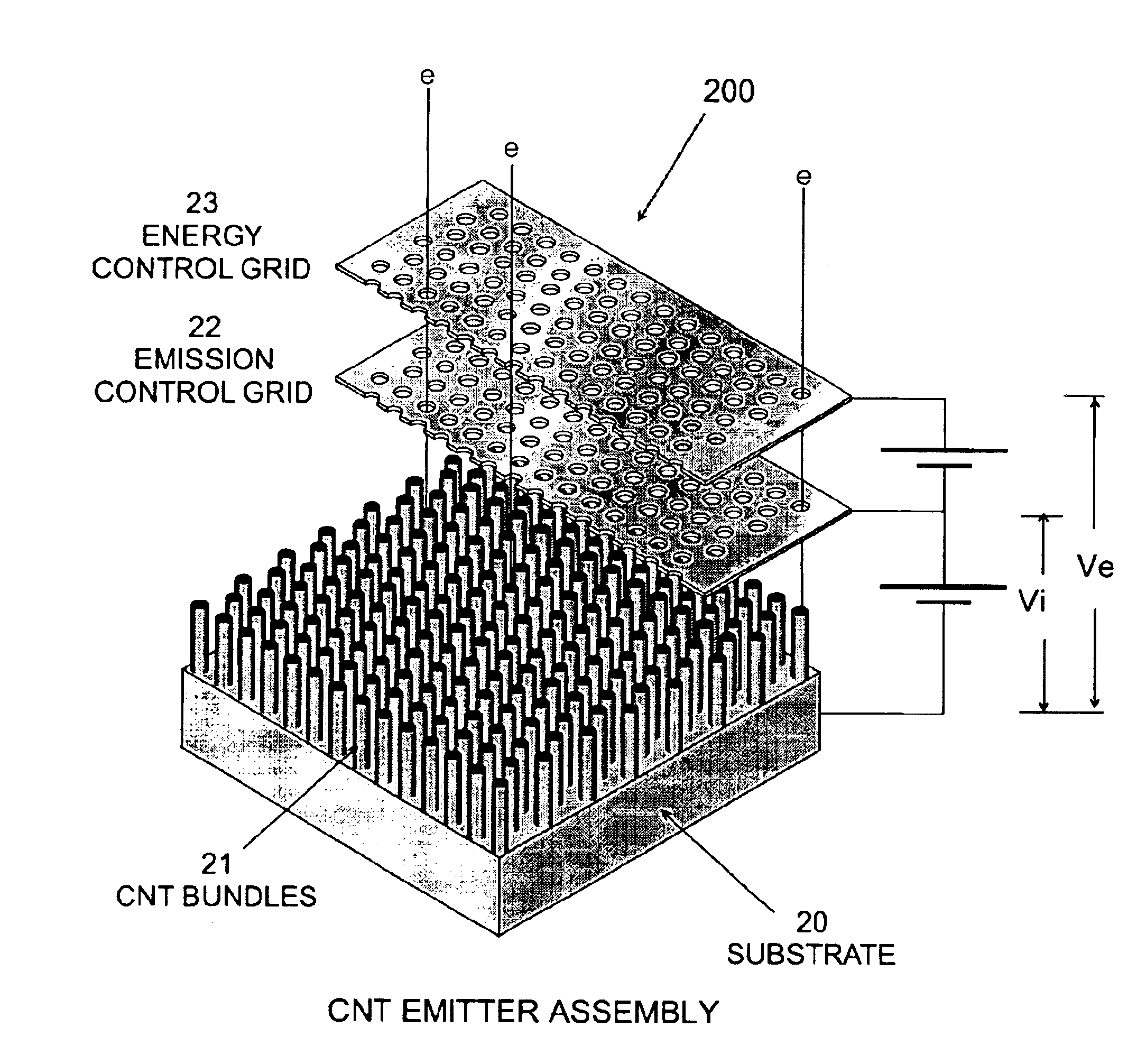
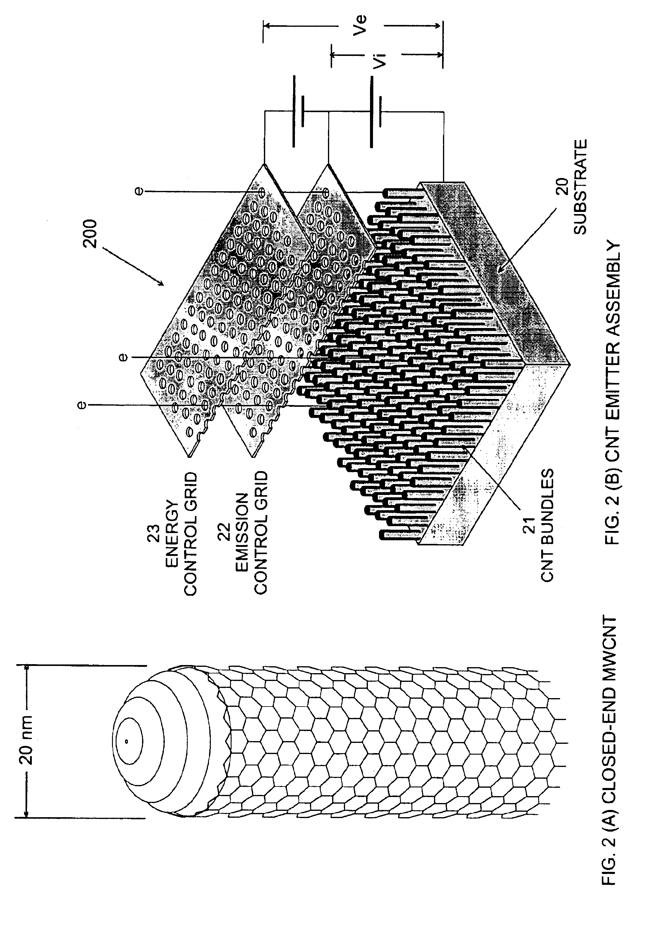
[0022]Embodiments of the present invention relate to ion sources for mass spectrometry. An ion source in accordance with embodiments of the invention is based on carbon nanotubes and can provide reliable electron beams for a long life time.

[0023]Carbon nanotubes (CNT) are seamless tubes of graphite sheets with full fullerene caps which were first discovered as multi-layer concentric tubes (i.e., multi-walled carbon nanotubes, MWCNT), as shown in FIG. 2A. Subsequently, single-walled carbon nanotubes (SWCNT) were prepared in the presence of transition metal catalysts. CNT have shown promising potentials in applications including nanonscale electronic devices, high strength materials, electron field emission, tips for scanning probe microscopy, gas storage, etc.

[0024]As electron field emitters, carbon nanotubes have the characteristics of low work function, durability, and thermal stability. Accordingly, an electron field emitter based on CNT can be driven at low voltage. In addition, ...


PUM

PropertyMeasurementUnit
energyaaaaaaaaaa
temperatureaaaaaaaaaa
conductiveaaaaaaaaaa

Abstract

An ion source for use in a mass spectrometer includes an electron emitter assembly configured to emit electron beams, wherein the electron emitter assembly comprises carbon nanotube bundles fixed to a substrate for emitting the electron beams, a first control grid configured to control emission of the electron beams, and a second control grid configured to control energies of the electron beams; an ionization chamber having an electron-beam inlet to allow the electron beams to enter the ionization chamber, a sample inlet for sample introduction, and an ion-beam outlet to provide an exit for ionized sample molecules; an electron lens disposed between the electron emitter assembly and the ionization chamber to focus the electron beams; and at least one electrode disposed proximate the ion-beam outlet to focus the ionized sample molecules exiting the ionization chamber.

Description

CROSS-REFERENCE TO RELATED APPLICATIONS[0001]Not Applicable.BACKGROUND OF INVENTION[0002]1. Field of the Invention[0003]The invention relates generally to ion sources for mass spectrometers, and, more particularly, to carbon nanotube-based ion sources for mass spectrometers.[0004]2. Background Art[0005]Mass spectrometers are powerful instruments for the analysis of a wide variety of samples. In order to perform mass analysis, the samples need to be vaporized. The gas molecules are then ionized by an ion source. An efficient ion source will convert as many sample molecules into ions as possible and produce an optimal beam for the specific type of analyzer. The most common ion source is the electron ionization (EI) source. In an EI source, electrons are produced by thermal emission from a hot filament, which is heated by a current flowing through it, located outside the ionization chamber. The electrons are accelerated by an electric field to a desired level of energy. This energy lev...

Claims


Application Information

Patent Timeline
Patent Type & Authority Patents(United States)
IPC IPC(8): H01J49/10H01J49/14H01J27/20H01J27/02
CPCB82Y10/00B82Y30/00H01J49/147Y10S977/939H01J2201/30434
Inventor TRAYNOR, PETER JOHNWRIGHT, ROBERT GEORGE
Owner THERMO ELECTRON A DE
Why Eureka
Try Eureka