Vibration tobacco stem sorting machine

A vibrating, finishing machine technology, applied in the direction of tobacco, tobacco processing, conveyor objects, etc., can solve problems such as single function

A vibrating, finishing machine technology, applied in the direction of tobacco, tobacco processing, conveyor objects, etc., can solve problems such as single function

CN102406229AInactive Publication Date: 2012-04-11YUNNAN KUNMING SHIPBUILDING DESIGN & RESEARCH INSTITUTE

Image

  • Vibration tobacco stem sorting machine
  • Vibration tobacco stem sorting machine
  • Vibration tobacco stem sorting machine

Examples


Embodiment Construction

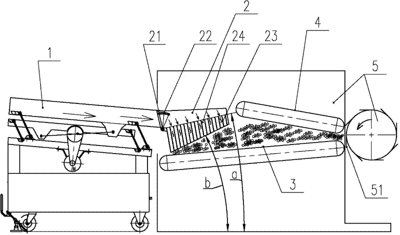
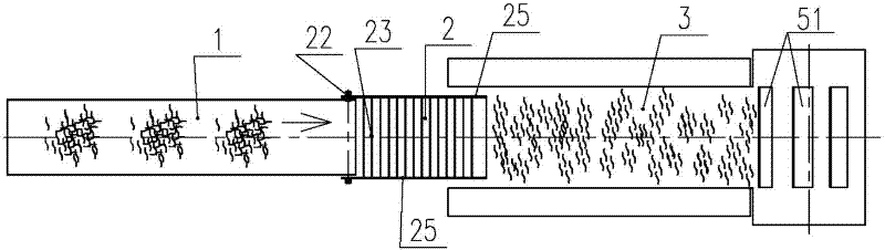
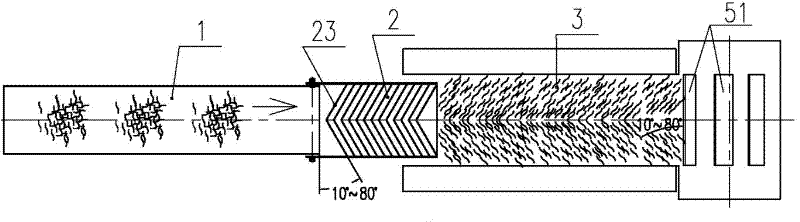
[0017] As shown in the figure, the present invention includes a vibrating conveying trough body 1 and a vibrating grid type chute 2 connected in sequence. Between the feeding ends of the row chain 3; the vibrating grating chute 2 is formed by connecting the separators 23 arranged at continuous equal intervals or gradually widening along the material flow direction to the side plates 25 on both sides, and the separators 23 and the two sides The side plates 25 separate and form continuous grid drains 24 . The upper edges of the continuously arranged partitions 23 rise block by block along the material flow direction to form a warping head on the top surface. The head-up angle a of the warping head on the top surface is 0-25°. The lower edges of the continuously arranged partitions 23 are also raised block by block along the material flow direction to form warps on the bottom. The head-up angle b of the warping head on the bottom surface is 5-45°. The separator 23 of the prese...


PUM


Abstract

A vibration tobacco stem sorting machine comprises a vibration conveying groove body (1) and a vibration grid type leakage groove (2) which are connected in turn. The vibration grid type leakage groove (2) is located between the feeding ends of an upper chain (4) and a lower chain (3) used for conveying the tobacco stems to a stem cutting machine (5). The vibration grid type leakage groove (2) is formed by horizontally connecting separation plates (23) which are continuously arranged in equal spaces or along the flow direction of the material in a widening meaner to lateral plates (25) at the two sides. The separation plates (23) and the lateral plates (25) are separated from each to form a continuous grid leaking groove (24). The invention can sort the tobacco stems as that the stem cutting angle is any one pre-set angle smaller than 90 degrees. The tobacco stems can enter a steam cutting machine according to the sorted postures. The structure is simple and reliable, and the sorting effect is good.

Description

technical field [0001] The invention relates to the technical field of tobacco stem sorting equipment for sorting disordered tobacco stems into required angles in the tobacco processing industry. Background technique [0002] In the tobacco processing industry, tobacco stems are often processed into shredded stems and blended into cigarettes to reduce tar content, increase the yield of raw materials, and improve the smoldering properties of cigarettes. Shredded stems are one of the main raw materials of cigarettes, and improving their quality can effectively improve the quality of cigarette products. The main indicators for assessing the quality of cut stems are: filling value, shape of cut stems, and resistance to curling of cut stems. Shredded tobacco stems generally need to be processed through the steps of remoisturizing tobacco stems, pressing stems, cutting stems, expanding, and drying. Among them, shredded stems have the greatest impact on the quality of cut stems. ...

Claims


Application Information

Patent Timeline
11 Apr 2012
Publication
CN102406229A
IPC
A24B7/14; B65G47/24
Inventors
张勇; 陆凌