

Spraying mechanical arm
A manipulator and arm technology, applied in the field of automatic machinery and equipment, can solve the problems of waste of raw materials, inconvenient operation process, difficult control of spraying distance and thickness, etc., and achieve the effect of reducing waste of raw materials and improving work efficiency.
- Summary
- Abstract
- Description
- Claims
- Application Information
AI Technical Summary
Problems solved by technology
Method used
Image

Examples
Embodiment Construction
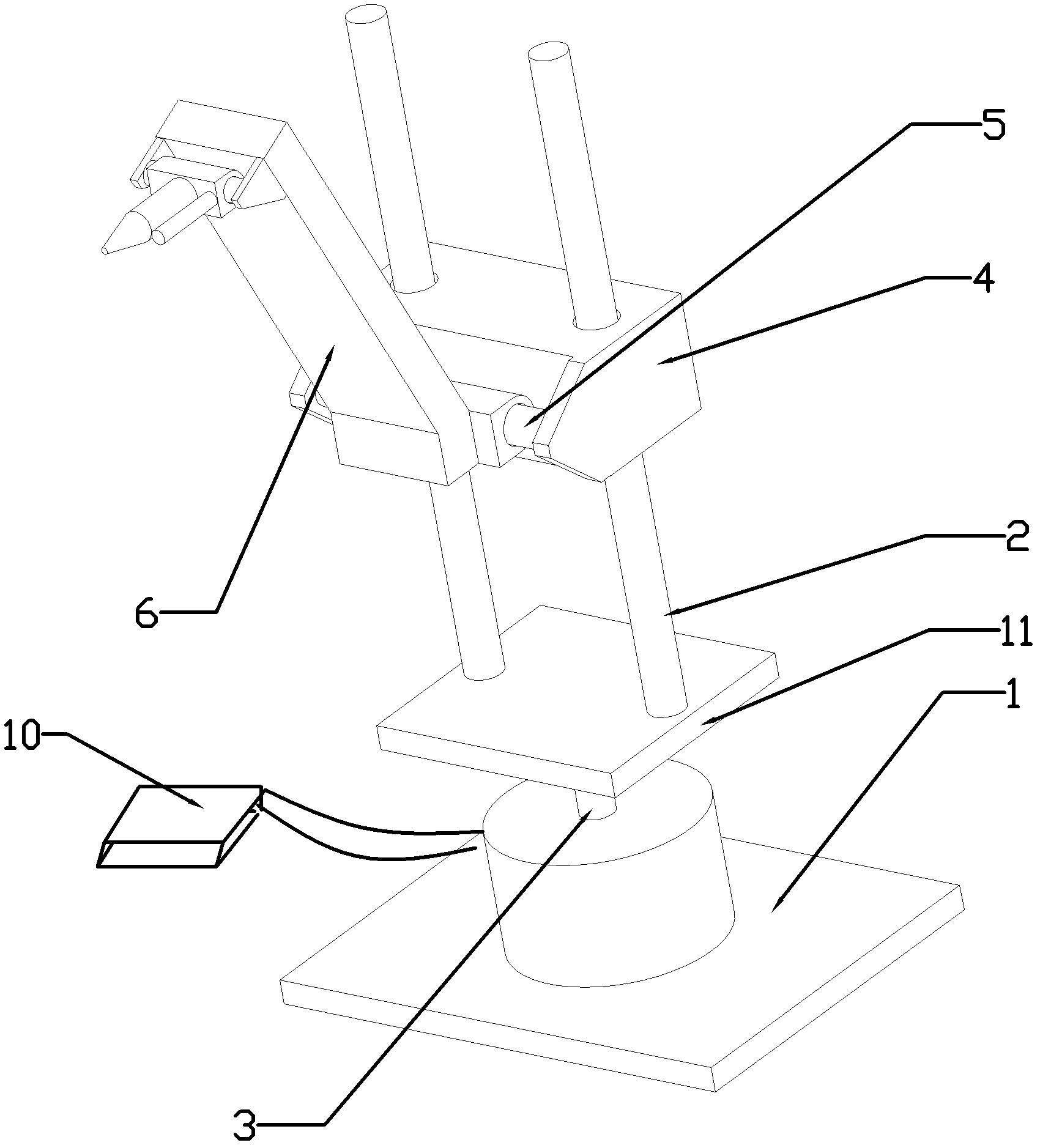
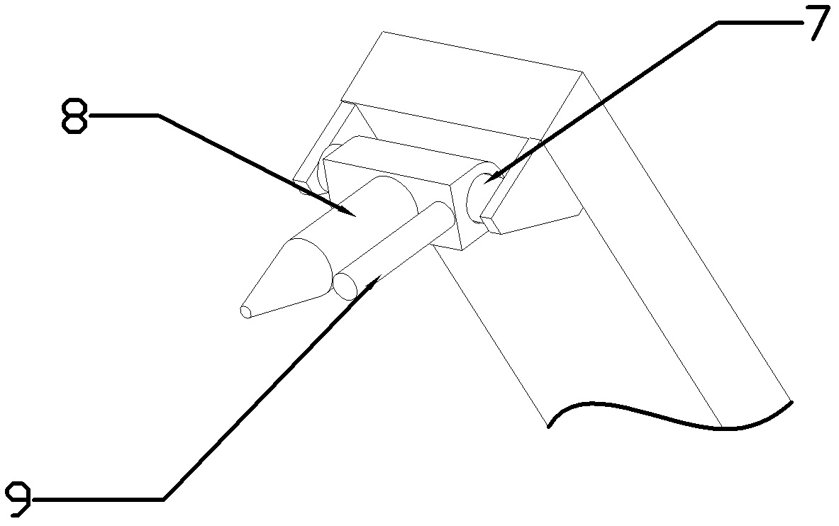
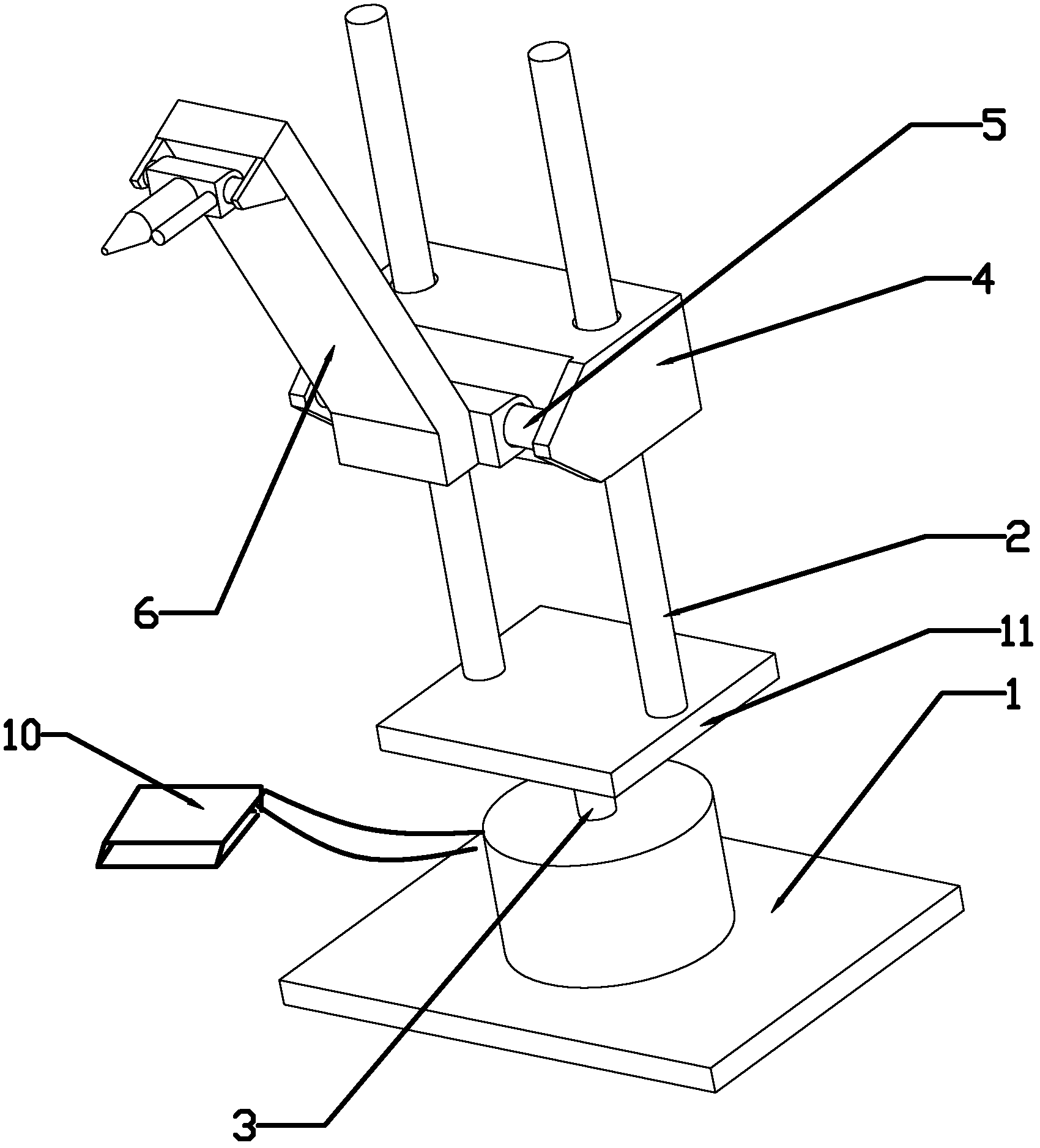
[0009] Such as figure 1 , figure 2 shown. A spraying manipulator, its structure is composed of a base 1, a column 2, a base rotating shaft 3, a sliding seat 4, an arm rotating shaft 5, an arm 6, a nozzle rotating shaft 7, a nozzle 8, a range finder 9, a control system 10 and a column base 11 , the lower end of the base shaft 3 is connected to the base 1 through a motor, the column base 11 is fixed on the upper end of the base shaft 3, the two columns 2 are fixed on the column base 11, the sliding seat 4 slides on the column 2, and the arm shaft 5 is fixed On the sliding seat 4, the arm 6 is connected to the sliding seat 4 through the arm rotating shaft 5, the nozzle rotating shaft 7 is fixed on the front end of the arm 6, the nozzle 8 is connected to the arm 6 through the nozzle rotating shaft 7, and the distance meter 9 is fixed on the side of the nozzle 8 One side of the base 1 is connected with a control system 10, the control system 10 is electrically connected with the...
PUM
 Abstract
Description
Claims
Application Information