
Multifunctional numerical control combined machine tool for machining shaft parts

A technology of combining machine tools and shaft parts, which is used in metal processing equipment, metal processing mechanical parts, manufacturing tools, etc., can solve the problem that the production line is too long and cannot be processed and milled at both ends of the reference center hole of shaft parts at the same time. End face processing, different processing methods, etc., to achieve the effect of reducing the floor space and shortening the assembly line

Inactive Publication Date: 2013-09-11
冯文波
View PDF6 Cites 0 Cited by
  • Summary
  • Abstract
  • Description
  • Claims
  • Application Information

AI Technical Summary

Problems solved by technology

The same point of the above two processing methods is that each single machine is sorted and processed. The difference is that the beat of the assembly line is tighter than that of the distributed processing, and the equipment used may be more
[0003] In recent years, with the modernization and development of machine tools, machine tools with multiple functions are constantly emerging, such as multi-functional turning centers, which can be used as the forming process of shaft parts, and have multiple processes such as turning, keyway milling, drilling, and tapping. Machining capability, and dual-spindle function for automatic docking and exchange of workpieces, but it cannot perform simultaneous processing of both ends of the reference center hole of shaft parts and simultaneous milling and end face processing of both ends. CNC milling end face punching center hole machine tools are used as shaft parts The benchmark machine tool can easily complete the simultaneous milling of both ends of the shaft parts and the machining of the benchmark center holes at both ends, but these two machine tools are difficult due to their different processes and clamping methods. Melting together can only be used in the production line as two separate machines with different functions connected in series in the processing of shaft parts. Difficulty on

Method used


Image

  • Multifunctional numerical control combined machine tool for machining shaft parts
  • Multifunctional numerical control combined machine tool for machining shaft parts
  • Multifunctional numerical control combined machine tool for machining shaft parts

Examples


Embodiment Construction

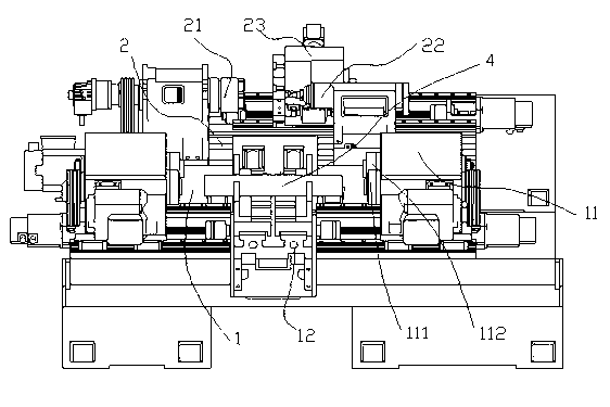
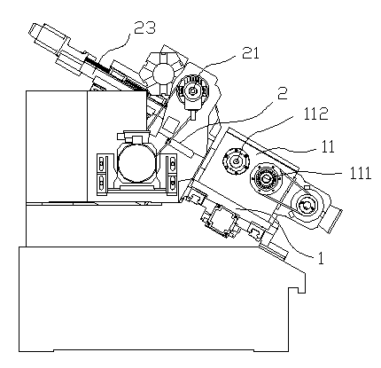
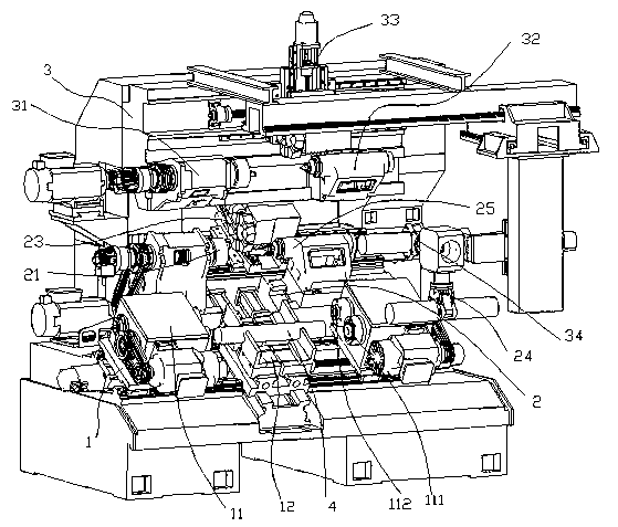
[0021] Such as figure 1 , 2 As shown in and 5, a multifunctional numerical control combined machine tool for processing shaft parts combined with two machine tools, the main work surface of the machine tool adopts a superimposed structure of two steps.

[0022] Wherein the first stepped surface 1 at the bottom is provided as an inclined plane, and the inclination of the inclined plane is 25°-45°. Both ends of the first stepped surface 1 are respectively provided with a spindle head 11 for milling the center hole of the end face. Each spindle head 11 is provided with a milling spindle 111 and a drilling spindle 112, which are respectively used for milling and drilling of the shaft 4. Center hole machining. A self-centering jig 12 is arranged in the middle of the first stepped surface 1 and can slide along the transverse sliding platform.

[0023] The second stepped surface 2 is an inclined surface hollowed out in the middle, and the second stepped surface 2 is set at the sam...


PUM


Abstract

The invention discloses a multifunctional numerical control combined machine tool for machining shaft parts. A worktop of a main body of the machine tool adopts an overlaying structure comprising at least two steps, a first step plane at the bottom is arranged to be an inclined plane, two ends of the first step plane are respectively provided with a spindle head for end plane milling and centre bore drilling, and the middle of the first step plane is provided with an automatic centering fixture; a second step plane is an inclined plane with the middle part being hollowed out, is arranged at an inclination as same as that of the first step plane, and is provided with a primary numerically controlled lathe; and a primary suspension type manipulator for automatically clamping workpieces up and down is arranged between the first step plane and the second step plane. In short, the multifunctional numerical control combined machine tool, which is disclosed by the invention, combines a standard machining machine tool and a form turning machine tool for the shaft parts, is supplemented by the suspension type manipulator for automatically clamping the workpieces up and down, and has the advantages of integrating milling the two end planes, sleeving the lathe, drilling centre bores at two ends, drilling centre bores, tapping the centre bores, turning, milling a keyseat, drilling holes on an excircle, tapping the excircle and other multiple operations.

Description

technical field [0001] The invention relates to a machine tool for processing shaft parts, in particular to a multifunctional numerical control combined machine tool for processing shaft parts. Background technique [0002] At present, the processing of shaft parts is completed by a variety of machine tools according to their process. For large batches, each single machine tool is sorted into a production line for processing. For small batches, each single machine is scattered and divided into sites. for processing. The same point of the above two processing methods is that each single machine is sorted and processed. The difference is that the beat of the assembly line is tighter than that of the distributed processing, and the equipment used may be more. [0003] In recent years, with the modernization of machine tools, multi-purpose machine tools are emerging, such as multi-functional turning centers, which can be used for forming and processing shaft parts. Machining c...

Claims


Application Information

Patent Timeline
Patent Type & Authority Patents(China)
IPC IPC(8): B23P23/00B23Q1/01
Inventor 冯文波
Owner 冯文波
Learn More