Supporting leg and applied crane thereof

A crane and movable outrigger technology, which is applied to the bottom support structure, the braking device of the lifting equipment, the load hanging element, etc., can solve the problem of excessive welding of the outrigger.

Active Publication Date: 2012-04-11
XUZHOU HEAVY MASCH CO LTD
View PDF7 Cites 5 Cited by
  • Summary
  • Abstract
  • Description
  • Claims
  • Application Information

AI Technical Summary

Problems solved by technology

[0010] Therefore, how to solve the problem caused by the excessive welding amount in the st...

Method used


Image

  • Supporting leg and applied crane thereof
  • Supporting leg and applied crane thereof
  • Supporting leg and applied crane thereof

Examples


Embodiment Construction

[0039] The core of the present invention is to provide an outrigger for a crane with less welding in the outrigger structure. Another core of the present invention is to provide a crane including the above outrigger.

[0040] In order to enable those skilled in the art to better understand the solutions of the present invention, the present invention will be further described in detail below in conjunction with the accompanying drawings and specific embodiments.

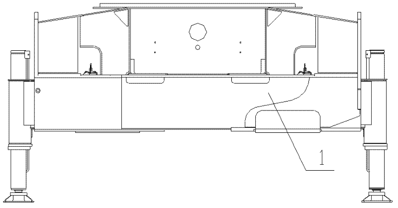
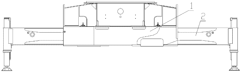
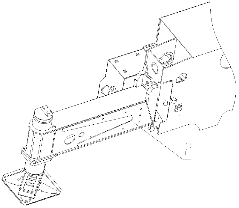
[0041] Please refer to Figure 7 to Figure 9 , Figure 7 The top view of the working state of the crane legs provided by the present invention, Figure 8 for Figure 7 A structural schematic diagram of a specific embodiment of a movable leg in the shown legs, Figure 9 for Figure 8 The sectional view of the B-B direction of the movable outrigger shown.

[0042]In a specific embodiment, the leg includes at least one movable leg 3, and the movable leg 3 is tailor-welded by a cover plate assembly 31, a left web a...


PUM


Abstract

The invention discloses a supporting leg of crane, which comprises at least one movable supporting leg; the movable supporting leg is formed in a manner that a cover plate assembly, a left web plate assembly, a right web plate assembly and a bottom plate are assembled and welded; each plate assembly comprises a base plate and a reinforced plate respectively; the reinforced plate is greater in thickness than the corresponding base plate and is butted, assembled and welded with the corresponding base plate to form the plate assembly; and the base plate in the plate assembly is located outside the reinforced plate. The movable supporting leg is formed in a manner that a cover plate assembly, a left web plate assembly, a right web plate assembly and a bottom plate are assembled and welded, and the base plate and the reinforced plate are assembled and welded, so that welding quantity is reduced. Concentrated and larger stress is formed at overlap joint position when the movable supporting leg is extended out, the reinforced plate is located inside and the overlap joint position is located on the reinforced plate so that the reinforced plate can adapt stress distribution of the plate assembly. The supporting leg of such structure adapts stress distribution of the plate assembly and reduces welding quantity. The invention also discloses a crane comprising the supporting leg.

Description

technical field [0001] The invention relates to the technical field of engineering machinery, in particular to a support leg of a crane. In addition, the present invention also relates to a crane comprising the above outrigger. Background technique [0002] With the rapid development of my country's economic construction, the application of cranes is becoming more and more extensive. With the continuous improvement of the tonnage of cranes, the application of outriggers in the field of cranes is increasing day by day. [0003] The outrigger is an important component of the crane. When the crane is in operation, the crane is first supported by the outrigger to stabilize it, and then the engineering operation is performed. The outrigger is generally located on both sides of the front and rear of the whole machine, and can be telescopic. [0004] Please refer to figure 1 and figure 2 , figure 1 It is a schematic diagram of a typical crane outrigger in non-operation state,...

Claims


Application Information

Patent Timeline
IPC IPC(8): B66C5/00
Inventor 马善华贾晓杰王新强龚彭
Owner XUZHOU HEAVY MASCH CO LTD
Why Eureka
Try Eureka