Automatic feed pocket patching machine

A technology of automatic material feeding and bag sticking machine, which is applied in the direction of cloth feeding mechanism, sewing machine components, floral stitch sewing machine, etc., which can solve the problems of not meeting the economical requirements of customers, increasing system complexity and failure rate, and increasing manufacturing costs, etc. , to achieve the effect of simple structure, optimized structure and improved automation level

Active Publication Date: 2012-04-11
JACK SEWING MASCH CO LTD
View PDF5 Cites 19 Cited by
  • Summary
  • Abstract
  • Description
  • Claims
  • Application Information

AI Technical Summary

Benefits of technology

This patented design allows for separate production and installation of various components such as feeder mechanisms or unloaders without affecting their functionality. It simplifies the overall process by allowing them to work together independently instead of being tied up individually at once. Additionally, it makes the entire system easier to install onto existing equipment due to its modular nature. Overall, this innovative solution improves the efficiency and reliability of bags produced through modern packaging machines while reducing costs associated therewith.

Problems solved by technology

This technical problem addressed in this patented describes a simplified design for a bag patcher machine used during fabrication processes such as sewn garments or washing machines. However, current designs have drawbacks including difficulty in separating different components from each other due to their large size, difficult maintenance, increased production time, excessively high labor intensity associated therewith, and potential safety hazards caused by improper use of these existing systems.

Method used


Image

  • Automatic feed pocket patching machine
  • Automatic feed pocket patching machine
  • Automatic feed pocket patching machine

Examples


Embodiment Construction

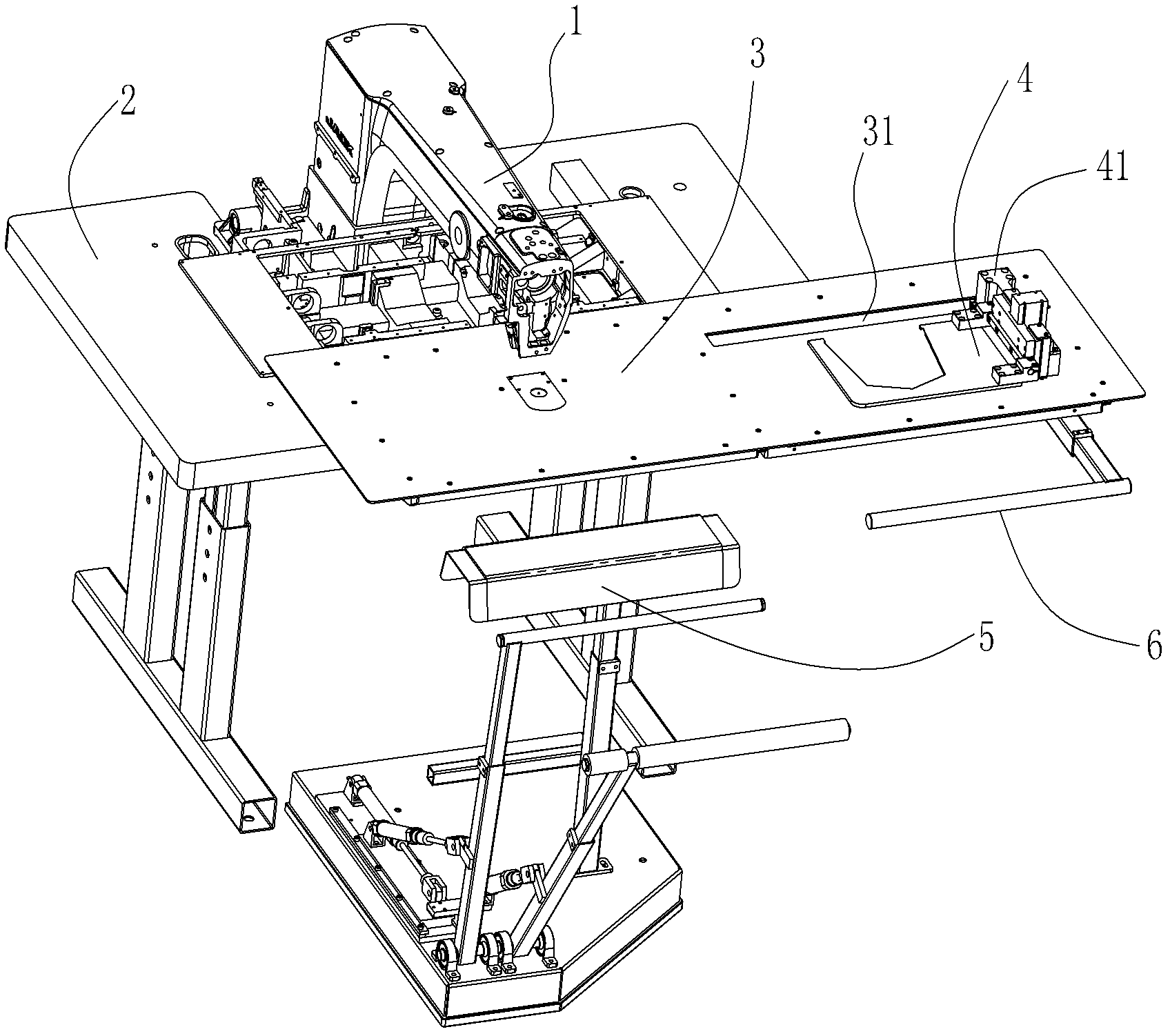
[0024] Such as figure 1 As shown, an automatic feeding bag attaching machine of the present invention includes a head 1, a platen 2, a template mechanism, a feeding mechanism 4, and a feeding mechanism 5. The feeding mechanism 4 is installed on a supplementary board 3, which is fixedly connected to the platform 2 and extends outward from the upper surface of the platform 2; the feeding mechanism 5 has an independent base and is placed on the supplementary board during operation. Below the outer side of the plate 3, but it is not connected to other mechanisms and can move freely. Therefore, the automatic feeding and patching machine of the present invention can be made completely new, or it can be used to upgrade and transform the existing patching machine that does not have the functions of automatic feeding and unloading. The feeding mechanism 4 installed on the auxiliary board 3 and the The unloading mechanism 5 with independent bases, as two relatively independent modules, c...


PUM


Abstract

The invention discloses an automatic feed pocket patching machine. The machine comprises a machine head, a bedplate, a template mechanism, a feed mechanism and a blanking mechanism; the feed mechanism comprises a linear drive device, a material pressing device, and an auxiliary plate which is fixedly connected with the bedplate and is extended outward from an upper surface of the bedplate; the template mechanism is positioned above the auxiliary plate; the blanking mechanism is positioned below the outer side of the auxiliary plate; the linear drive device is arranged below the auxiliary plate; the material pressing device is positioned on the auxiliary plate; the linear drive device is connected with a connection seat through the material pressing device; and the auxiliary plate is provided with a sliding groove through which the connection seat passes. Due to the adoption of a modular structure, the feed mechanism and the blanking mechanism become independent modules, the manufacturing and assembly complexity of a product can be reduced and manufacturing cost can be reduced.

Description


Claims


Application Information

Patent Timeline
Owner JACK SEWING MASCH CO LTD
Why Eureka
Try Eureka