Bearing Assembly

一种轴承装置、轴承圈的技术,应用在轴承装置领域,能够解决轴承磨损加大、轴承非圆形等问题,达到好运转的效果

Inactive Publication Date: 2012-04-11
AB SKF
View PDF5 Cites 6 Cited by
  • Summary
  • Abstract
  • Description
  • Claims
  • Application Information

AI Technical Summary

Problems solved by technology

[0004] The unfavorable result is increased wear of the bearing and a non-circular running of the bearing as a whole

Method used


Image

  • Bearing Assembly
  • Bearing Assembly
  • Bearing Assembly

Examples


Embodiment Construction

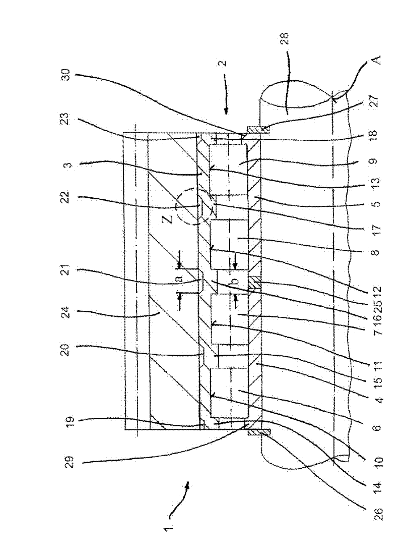
[0022] exist figure 1 The figure schematically shows a bearing arrangement 1 , by means of which a gear 24 of a planetary gear of a wind power plant is supported on a shaft 28 . Since the gear wheel 24 is a helical spur gear, axial forces also arise during operation which must be absorbed by the rolling bearing 2 of the bearing arrangement 1 .

[0023] The rolling bearing 2 is designed as a four-row cylindrical roller bearing. In this case, the outer ring 3 of the bearing is designed in one piece (but this is not mandatory); A radially inwardly extending rib 15 , 16 , 17 is provided between the two raceways. Ribs 14 and 18 are located in the axial end region of outer ring 3 .

[0024] The rolling bearing 2 has two inner rings 4 and 5 with corresponding inner ring raceways. A spacer ring 25 is provided between the two inner rings 4 and 5 . Each of the two inner rings 4 , 5 has ribs 29 and 30 in the region of the axial ends of the rolling bearing 2 . Axial forces can thus ...


PUM


Abstract

A roller bearing comprises at least two rows of rollers disposed between an inner ring and an outer ring. At least two tracks guide the respective rows of roller and are defined in the axial direction of the inner ring or the outer ring. At least one flange abuts axial ends of axially-adjacent rows of rollers and extends radially from a radially outer side or a radially inner side of the inner ring or the outer ring. At least one recess is defined on the side of the inner ring or the outer ring that is opposite of the radially outer side or the radially inner side of the inner ring or the outer ring, from which the at least one flange radially extends. The at least one recess at least partially overlaps the at least one flange in the axial direction.

Description

technical field [0001] The invention relates to a bearing arrangement comprising an at least two-row rolling bearing having at least one outer ring, at least one inner ring and at least two rows of rolling bodies arranged between the inner ring and the outer ring, wherein at least one bearing The ring has at least two side-by-side raceways for the rolling bodies, and a radially extending rib for axially delimiting the rolling bodies is provided at least between the two raceways. Background technique [0002] Bearing arrangements of this type are sufficiently known in the prior art. In order to be able to withstand a large supporting force, multiple rows of rolling elements arranged in parallel are provided. For example, four-row cylindrical roller bearings can be used for supporting the rotor of a wind energy plant, whereby high radial forces can be transmitted. Bearings of this type can also be used, for example, in the described application for supporting gear wheels of ...

Claims


Application Information

Patent Timeline
Patent Type & Authority Applications(China)
IPC IPC(8): F16C19/36F16C33/58F03D11/00
CPCF16C2300/14F16C19/28F16C33/64F16C33/586F16C2360/31F16C2240/42Y10T74/19953
Inventor A.奥尔谢夫斯基A.斯图本劳克
Owner AB SKF
Why Eureka
Try Eureka