Load sensor

A load sensor, ring-shaped technology, applied in the field of sensors, can solve the problems of affecting the measurement accuracy of the sensor, permanent deformation of the elastic body, and inconvenient application.

Active Publication Date: 2013-06-05
PUTIAN LITIAN MEASURING & CONTROLLING TECH
View PDF6 Cites 0 Cited by
  • Summary
  • Abstract
  • Description
  • Claims
  • Application Information

AI Technical Summary

Problems solved by technology

[0003] The force sensor is often disturbed by the lateral force during use, which affects the measurement accuracy of the sensor's forward force. Some lateral forces are too large and cause permanent deformation of the elastic body
In order to reduce the influence of lateral force, the common load sensor adopts a spherical pressure bearing head on the pressure bearing surface. Although this structure can control the influence of lateral force in a very small range, it cannot withstand strong lateral force. , in order to enable the force sensor of this structure to work in an environment with a large lateral force, it is generally necessary to install an auxiliary protective structure between the force sensor and the structure to be measured, which is very inconvenient for the application and is not suitable for installation in space Small or harsh environments

Method used


Image

  • Load sensor
  • Load sensor

Examples


Embodiment Construction

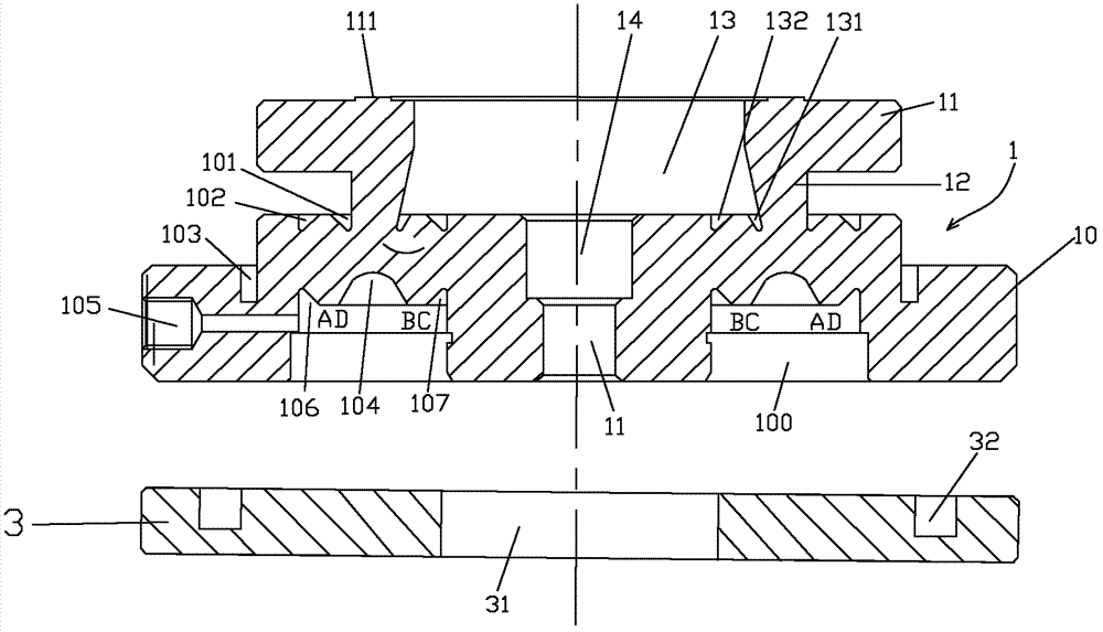
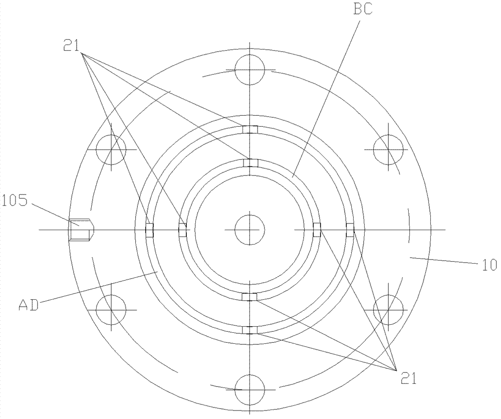
[0023] See figure 1 with 2 , The embodiment of the present invention is provided with a stressed elastic body 1, a strain gauge group (composed of 8 strain gauges 21) and a bottom cover 3.

[0024] The stressed elastic body 1 is provided with central through holes 13, 14 and 11, and the central through holes 13, 14 and 11 are coaxial central through holes with upper and lower steps. The force-receiving elastic body 1 is sequentially provided with a coaxial force-receiving platform 11, a force guiding column 12 and a stepped base 10 from top to bottom. The force platform 11 is provided with an annular force plane 111, and the bottom surface of the central through hole 13 is provided with a first annular force guide angle 131 extending obliquely downward along the bottom of the inner wall of the force guide column 12 and a first annular force guide angle located at the first annular force guide angle. The second annular force guiding angle 132 next to 131, the first annular force g...


PUM


Abstract

The invention relates to a sensor, more particularly to a load sensor. The load sensor comprises a stressed elastic main body, a strain gauge set and a bottom cap. Central through holes are arranged at the stressed elastic main body; and a stressed platform, a force guide post and a stepped pedestal are arranged at the stressed elastic main body from top to bottom, wherein the stressed platform, the force guide post and the stepped pedestal are arranged coaxially. An annular stressed plane is arranged on the stressed platform; and a first annular force guide angle that is extended downwardly along the bottom of the inner wall of the force guide post is arranged at a step surface of the top central through hole. The pedestal is a two-layer stepped pedestal; the upper layer surface of the pedestal is provided with a first annular force guide groove that is extended downwardly along the periphery of the bottom of the outer wall of the force guide post; the lower layer surface of the pedestal is provided with an annular stressed isolation groove that is extended downwardly along the periphery of the bottom of the upper layer outer wall of the pedestal; annular grooves are arranged at the bottom of the pedestal and annular stressed releasing grooves are arranged at bottoms of the annular grooves; annular paster surfaces are arranged at bottoms of the annular grooves; and a lead hole that is communicated with the lower layer periphery of the pedestal is arranged at a side wall of one of the annular grooves. Besides, the strain gauge set is arranged on the strain gauge set; and leads of the strain gauge set is externally connected to a measuring circuit or a strain gauge through the lead hole.

Description

Technical field [0001] The invention relates to a sensor, in particular to a load sensor. Background technique [0002] Most of the existing load force sensors are strain gauge sensors. The principle is that the deformation of the elastic body after the force causes the strain gauge to deform, changing the force signal into a strain voltage signal that we can measure. There are many types of sensors. At present, the common types of force are divided into tension and pressure sensors (column type, plate ring type, barrel type, etc.), bending type (equal strength beam, box beam), shear type (spoke type, square beam, etc.) Round section I-beam, etc.). [0003] The force sensor is often interfered by the lateral force during use, which affects the measurement accuracy of the sensor's positive force, and some excessive lateral force can also cause permanent deformation of the elastic body. In order to reduce the influence of lateral force, the common load sensor adopts spherical press...

Claims


Application Information

Patent Timeline
Patent Type & Authority Patents(China)
IPC IPC(8): G01G3/13G01G21/30
Inventor 徐天宝徐光源陈梅红
Owner PUTIAN LITIAN MEASURING & CONTROLLING TECH
Why Eureka
Try Eureka