

Solar cell module
A technology for solar cells and solar panels, which is applied in the directions of solar thermal power generation, solar thermal energy, solar thermal collectors, etc., can solve the problems of reduced load resistance performance of transparent substrates of solar panels, etc., so as to improve the low load resistance and restrain damage. , the effect of alleviating the concentration of local stress
- Summary
- Abstract
- Description
- Claims
- Application Information
AI Technical Summary
Problems solved by technology
Method used
Image

Examples
Embodiment approach 1
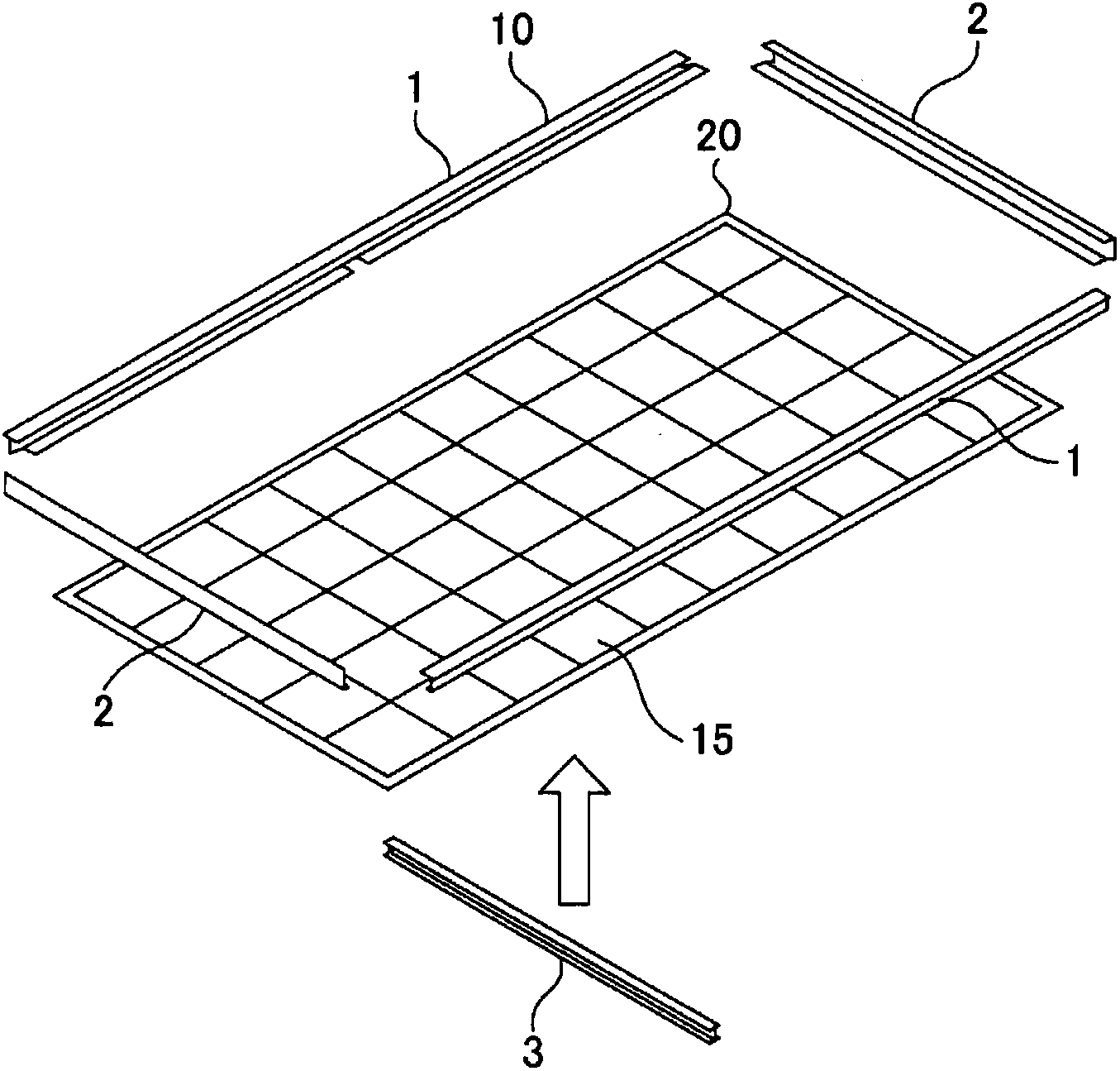
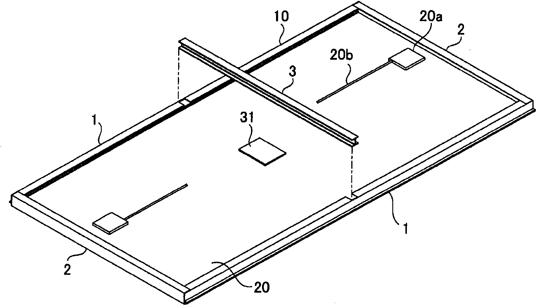
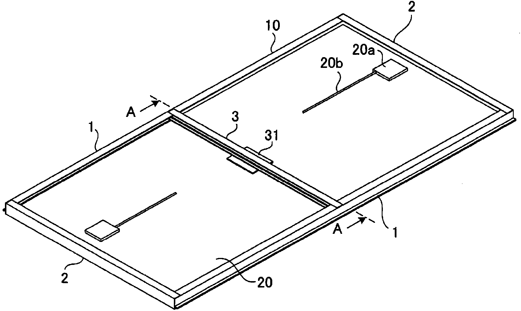
[0039] figure 1 It is a perspective view showing the state of the initial step of assembling the solar cell module of the present invention. figure 2 It is a perspective view showing a state in which a reinforcement frame is attached to an intermediate assembly having a frame-shaped frame attached to an outer edge of a solar cell panel from the back. image 3 It is a perspective view showing a state in which the attachment of the reinforcing frame to the intermediate assembly is completed.
[0040] The solar cell module has: a substantially rectangular flat solar cell panel 20; a buffer material 31 fixed to the back surface of the solar cell panel 20; and a rectangular frame-shaped frame 10 surrounding the outer edge of the solar cell panel 20 throughout. ; The reinforcement frame 3 installed on the frame-like frame 10 . The buffer material 31 is fixed at a position sandwiched between the solar cell panel 20 and the reinforcement frame 3 .
[0041] like figure 1 As show...
Embodiment approach 2
[0051] Figure 8 It is a perspective view showing a state in which the cushioning material of Embodiment 2 of the solar cell module of the present invention is interposed between the solar cell panel and the reinforcing frame. Figure 9 It is a figure which shows the state which looked at the cushioning material of Embodiment 2 from three directions. like Figure 8 as well as Figure 9 As shown, in the buffer material 32 of this embodiment, the first main surface facing the solar cell panel 20 is formed as a substantially flat flat surface 32 a so as to be in flat contact with the solar cell panel 20 .
[0052] On the other hand, on the second main surface facing the reinforcement frame 3, a plurality of protrusions 32b extending in a direction perpendicular to the reinforcement frame 3 are formed, and the corner lines (tops) that smoothly connect these plurality of protrusions 32b are formed. surface) becomes a curved surface 32b of an arcuate cross-section that forms the ...
Embodiment approach 3
[0056] Figure 11 It is a perspective view of a buffer material in Embodiment 3 of the solar cell module of the present invention. Figure 12 It is a schematic diagram showing a state in which the reaction force from the reinforcing frame side is dispersed by the cushioning material of the third embodiment. The buffer material 33 of the present embodiment is formed in a substantially rectangular parallelepiped flat shape, and the first main surface facing the solar cell panel 20 is a flat surface 33 a. In addition, notches 33 b are respectively provided at the center portions of both ends in the longitudinal direction of the reinforcement frame 3 on the second principal surface facing the reinforcement frame 3 . In other words, the notch 33b is provided at the center of the reinforcement frame 3 side of both longitudinal end faces of the reinforcement frame 3 . That is, the notch 33b is provided at a point different from the existing local stress concentration point P ( Im...
PUM
 Abstract
Description
Claims
Application Information