Ultrasonic condensing and separating device with multiple air inlet nozzles

The technology of an intake nozzle and a separation device is applied in the field of multiple intake nozzle type supersonic condensation and separation devices, and can solve the problems of weak swirling capability of the cyclone device, unfavorable droplet growth, and reduced separation efficiency of the supersonic separator, etc. The effect of improving separation efficiency and reducing the effect of droplet re-evaporation

Inactive Publication Date: 2012-04-18
文闯
View PDF22 Cites 11 Cited by
  • Summary
  • Abstract
  • Description
  • Claims
  • Application Information

AI Technical Summary

Problems solved by technology

[0005] There are two main core technologies of the supersonic cyclone separator: one is to install the supersonic wing in the supersonic section behind the nozzle to generate swirling flow, but since the speed conversion occurs under supersonic conditions, shock waves are easily generated behind the supersonic wing , destroys the low temperature and low pressure environment, is not conducive to the growth of droplets, and reduces the separation efficiency of the supersonic separator. Representative patents mainly include foreign US 6513345B1, US 6524368B2, US 3773825B2, US 6962199B1, US 7261766B2, US 7318849B2, US 7494535B2, WO 2003 / 092850A1, WO 2004 / 020074A1 and domestic ZL 200410074338.8, etc.; the other is to install the swirl device at the inlet of the nozzle, so that the gas enters the nozzle in the form of swirl to expand and cool down. The main patents are foreign 的US 7357825B2、US 2008 / 0196581A1、US 2010 / 0147021A1、EP 1131588B1、US 6372019B1、US 2010 / 0147023A1和国内的ZL200810011258.6、ZL 200910023458.8及申请号200910024347.9、200910081813.7、200910093744.1、201010597341.3等,不足之处是旋 The swirling capacity of the flow device is weaker than that of the supersonic wing, which reduces the separation effect of the supersonic separator

Method used


Image

  • Ultrasonic condensing and separating device with multiple air inlet nozzles
  • Ultrasonic condensing and separating device with multiple air inlet nozzles
  • Ultrasonic condensing and separating device with multiple air inlet nozzles

Examples


Embodiment Construction

[0015] The structural features and working principles of the present invention will be further described below in conjunction with the accompanying drawings.

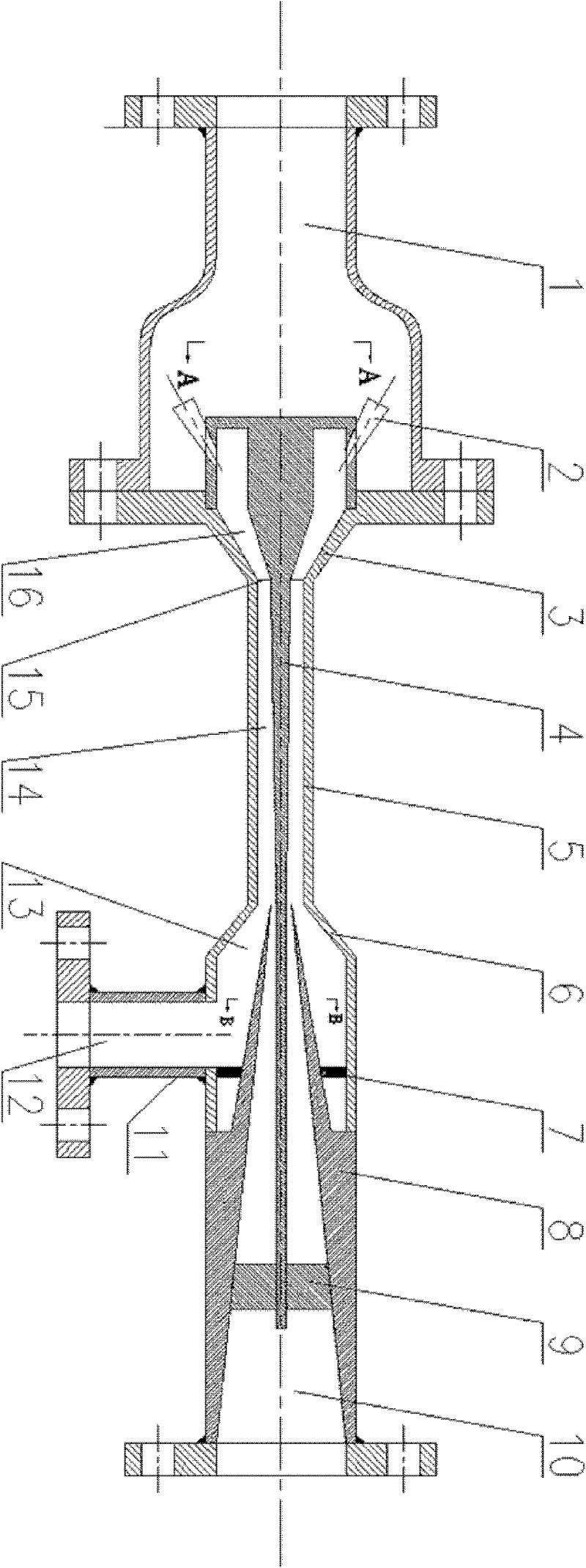
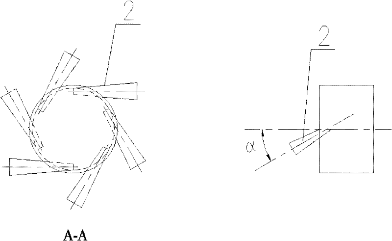
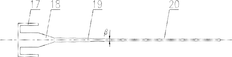
[0016] see figure 1 , 3, the present invention includes air intake chamber 1, air intake nozzle 2, contraction section 3, central body 4, outer straight pipe section 5, expansion section 6, positioning support rib 7, diffuser pipe 8, vortex arrester 9, dry gas Outlet 10, effusion cavity 13, drain tube 11 and liquid outlet 12; central body 4 includes straight tube 17, constriction cone section 18, tapering cone section 19 and cylindrical section 20, constriction section 3 and constriction section from left to right The conical section 18 forms an annular subsonic constriction channel 16 with a gradually decreasing area, the outer straight pipe section 5 and the tapering cone section 19 form an annular supersonic swirl separation channel 14 with a gradually increasing area, and the annular subsonic constriction channel 16...


PUM


Abstract

The invention discloses an ultrasonic condensing and separating device with multiple air inlet nozzles, which is mainly applied in the field of gas separation. Multiple air inlet nozzles are uniformly arranged in an air inlet cavity for making gas tangentially enter in a flow channel; the radius of the section of a contraction flow channel is reduced gradually, so that the rotational flow is enhanced according to the angular momentum conservation law, and huge centrifugal force is generated; a central body is arranged in the center of the flow channel, and constructs an annular contraction-expansion spray pipe with a variable sectional area together with a contraction section and a straight pipe section; a subsonic contraction flow channel, a throat part and a supersonic rotational flow separation flow channel are formed; after gas is accelerated to an ultrasonic speed, and low temperature and low pressure are formed, condensable components are condensed; at an ultrasonic rotational flow separation section, rotational flow separation of gas and liquid is realized by using huge centrifugal force; and the liquid enters a liquid accumulating cavity, and dry gas is collected in the center of the flow channel, enters a diffuser for returning pressure, and flows out. The device has the advantages of simple structure, no movable component, high processing accuracy, small occupied space, no need of adding any chemical medicament and support of unmanned operation, and is particularly suitable for use on offshore platforms.

Description

Technical field: [0001] The invention relates to a supersonic low-temperature condensation and cyclone separation technology of multi-component mixed gas, in particular to a multi-inlet nozzle type supersonic condensation separation device. Background technique: [0002] With the rapid development of social economy, the world economy is increasingly dependent on energy. Especially in my country, fossil energy still occupies a large proportion of primary energy consumption. Compared with coal and petroleum, natural gas has the advantages of high calorific value, cleanliness, safety and convenience, and has broad development prospects. However, natural gas extracted from imports is often saturated with water vapor and contains some heavy hydrocarbon components. In order to meet the requirements of natural gas export and use, it is necessary to separate water vapor and heavy hydrocarbon components. However, traditional natural gas separation processes, such as cooling, absorpt...

Claims


Application Information

Patent Timeline
Patent Type & Authority Applications(China)
IPC IPC(8): B01D53/24B01D45/16B01D5/00E21B43/34
Inventor 文闯曹学文杨燕
Owner 文闯
Why Eureka
Try Eureka