Casting machine

A casting machine and frame technology, applied in the field of casting machines, can solve problems such as shortening production takt time, and achieve the effect of shortening production takt time

Inactive Publication Date: 2012-04-18
青木伸藏
View PDF6 Cites 9 Cited by
  • Summary
  • Abstract
  • Description
  • Claims
  • Application Information

AI Technical Summary

Problems solved by technology

This prior art achieves energy saving by driving the mold electrically, but according to further research by the applicant, it was found that there is still room for improvement in terms of further shortening the takt time.

Method used


Image

  • Casting machine
  • Casting machine
  • Casting machine

Examples


Embodiment 1

[0024] Hereinafter, the present invention will be specifically described based on illustrated embodiments.

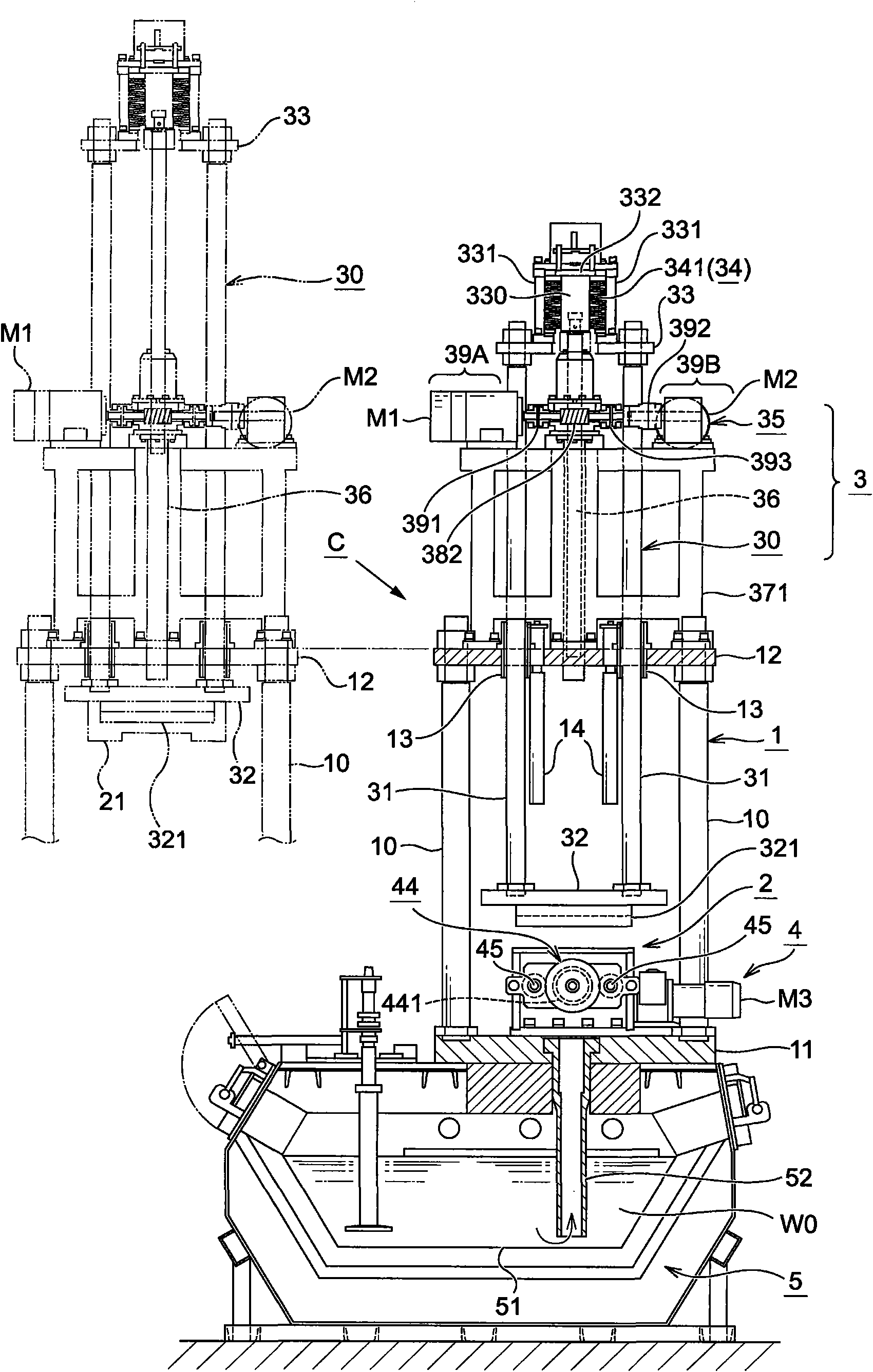
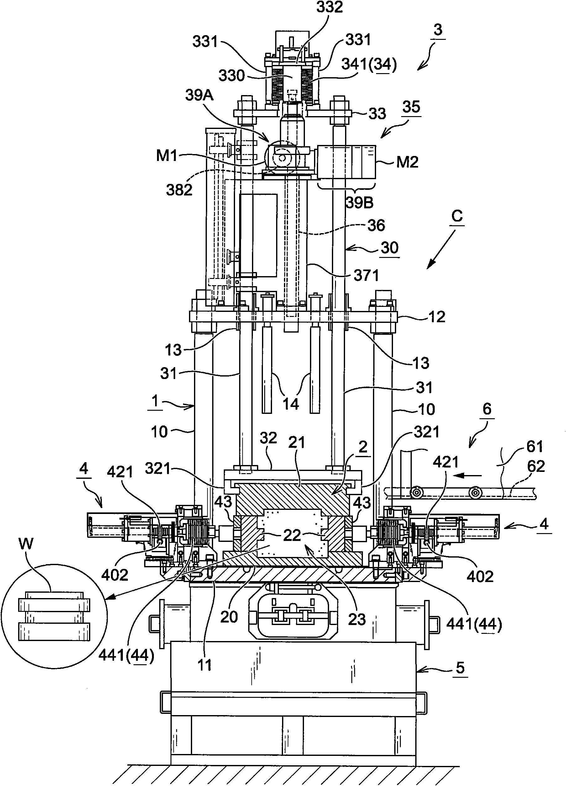
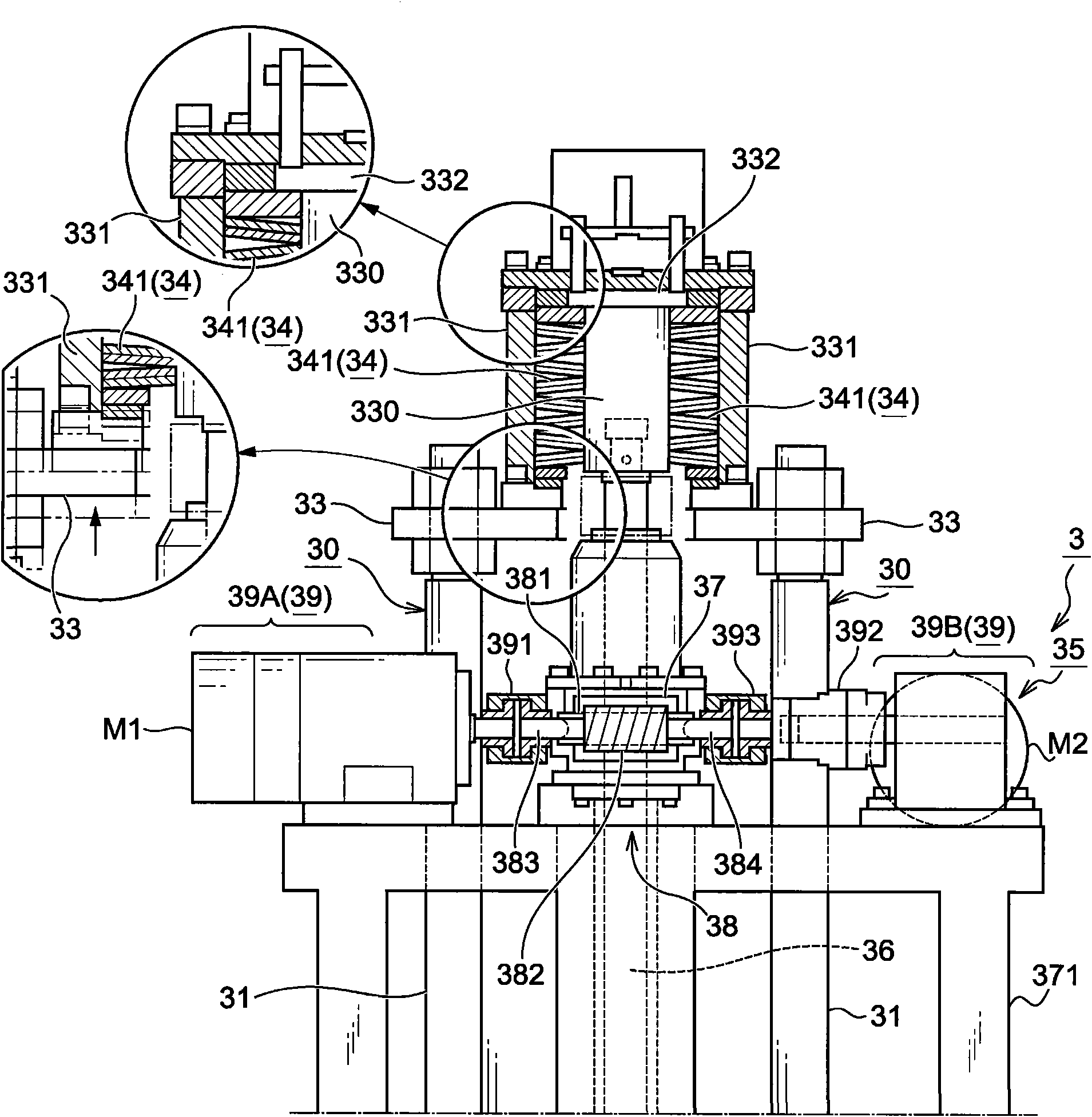
[0025] The casting machine C of the present invention comprises: a frame 1; a mold device 2 supported on the frame 1; a lifting device 3 for driving the upper mold 21 of the mold device 2 to lift; a transverse mold 22 for driving the mold device 2 A lateral moving device 4 for lateral movement; a liquid storage device 5 that communicates with the lower mold 20 of the mold device 2 and is arranged below the frame 1 ; and an unloading device 6 for unloading manufactured workpieces W.

[0026] First, rack 1 will be described.

[0027] As an example, the frame 1 is a frame-shaped member that integrally supports a base support plate 11 and an upper support plate 12 arranged above the base support plate 11 in a layered manner by utilizing four columns 10 . Metal sliding pipes 13 for supporting the lifting device 3 are provided. In addition, a workpiece take-out lever 14 is ...


PUM


Abstract

The invention provides a casting machine, which is based on lifting of an upper mold of a casting device through a motor-driven ball screw mechanism and aims to further reduce the production cycle time. Even if a mold has a complex shape with combination of a horizontal mold in addition to an upper mold and a lower mold, casting can be carried out smoothly. The casting machine (C) comprises a base bearing plate (11), a rack (1), a mold device (2) and a lifting device (3), and molten metal materials (W0) are injected into the mold device (2) to be cured and cast into a specified shape. The casting machine is characterized in that the lifting device (3) comprises a lifting rack (30) and a lifting drive device (35), the lifting rack (30) comprises a lifting rod (31), a lifting base (32) and a top plate (33), the lifting drive device (35) adopts the motor-driven ball screw mechanism as a driving mechanism, and the ball screw mechanism is connected with a drive input mechanism (39) for a high-speed input system and a high-load input system.

Description

technical field [0001] The present invention relates to a casting machine, and in particular, relates to an improvement of a casting machine capable of achieving more efficient associated operations accompanying casting operations, achieving operational reliability, and reducing operating costs. Background technique [0002] The general structure of the casting machine adopts such a structure: it includes a frame in the shape of connecting the base support plate and the upper support plate with a column, a mold device installed on the base support plate of the frame, and a mold device that can be positioned relative to the frame. The upper support plate of the upper support plate is supported up and down on the upper support plate, and the lifting device of the upper mold of the mold device can be lifted at the lower end, and the molten metal raw material is injected into the cavity in the mold device and solidified to make the product Manufactured into a prescribed shape. ...

Claims


Application Information

Patent Timeline
Patent Type & Authority Applications(China)
IPC IPC(8): B22D18/04B22D18/06
Inventor 青木伸藏
Owner 青木伸藏
Why Eureka
Try Eureka