Clamping device and clamping method

A clamping device and clamping technology, used in positioning devices, clamping, maintenance and safety accessories, etc., can solve the problems of high processing intermittent and high consumption, and achieve the effect of reliable and repeatable processing.

Inactive Publication Date: 2012-04-18
GROB WERKE & K G
View PDF9 Cites 12 Cited by
  • Summary
  • Abstract
  • Description
  • Claims
  • Application Information

AI Technical Summary

Problems solved by technology

There is a considerable risk of the object tilting on these clamping devices, with the result that undesired machining pauses occur or that high expenditure is required for possible precise feeding and ejection of the object

Method used


Image

  • Clamping device and clamping method
  • Clamping device and clamping method
  • Clamping device and clamping method

Examples


Embodiment Construction

[0042] In the figures, identical or mutually equivalent elements are each provided with the same reference symbols and are therefore not described again unless this is expedient.

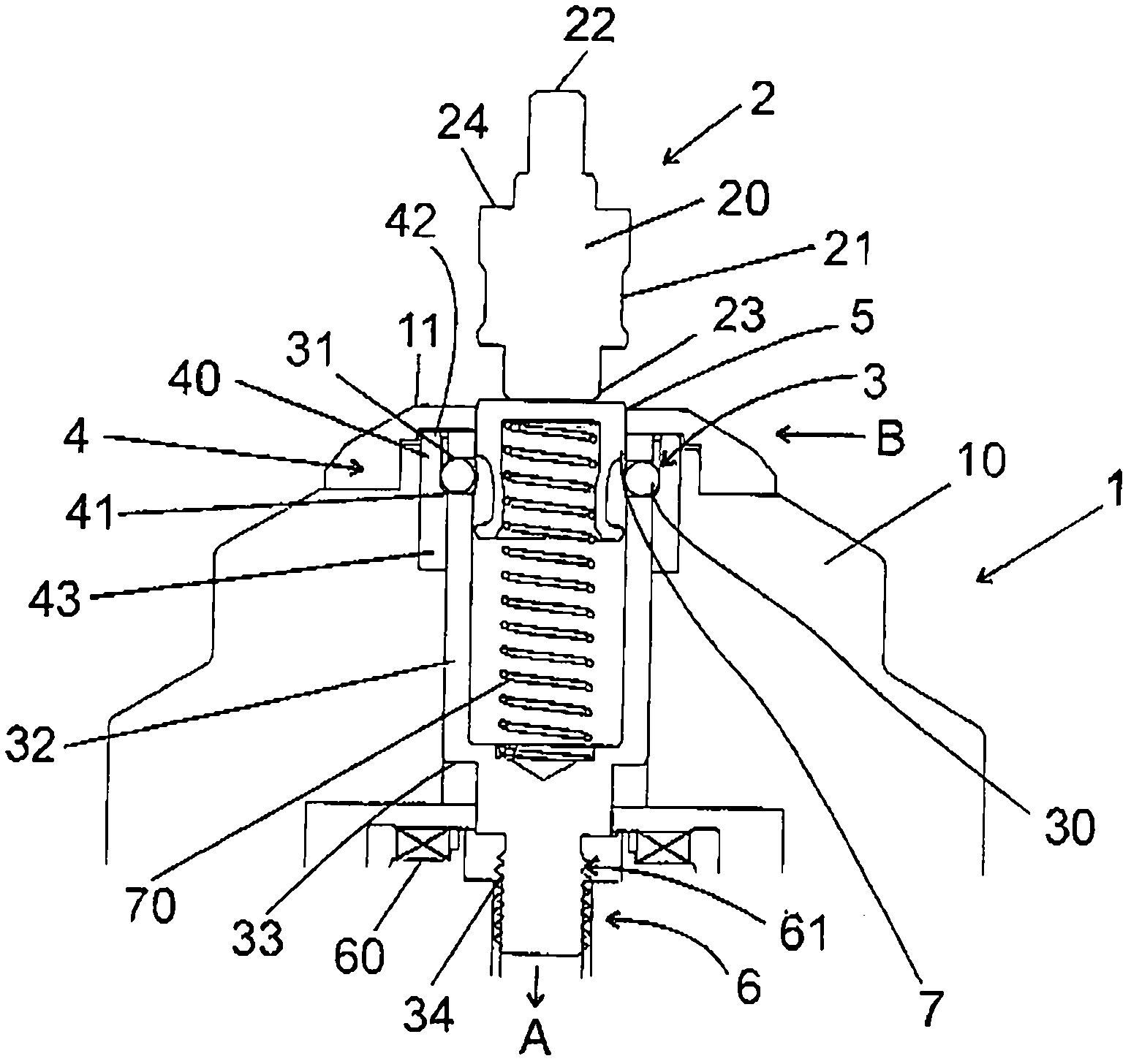
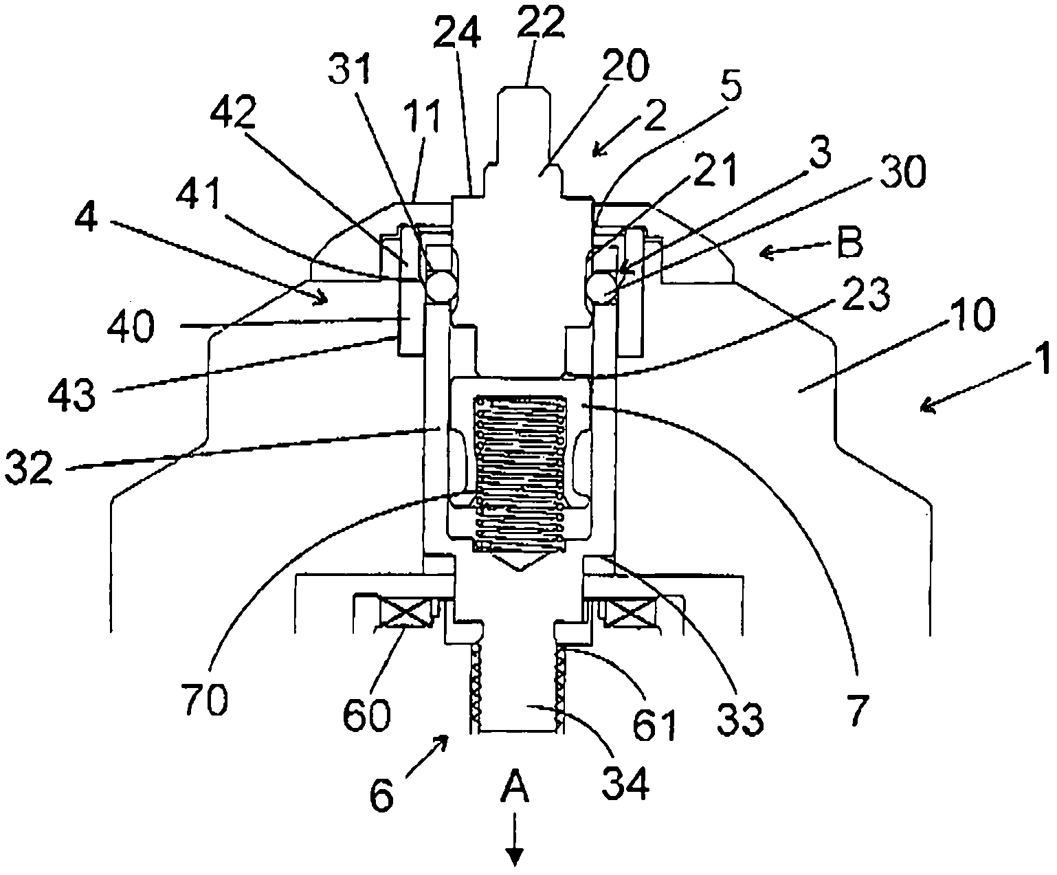
[0043] figure 1 A preferred embodiment of the clamping device 1 according to the invention is shown. The clamping device comprises a clamping element 3 and a clamping drive 6 . A clamping device 2 is assigned to the clamping device 1 , which can be arranged, for example, on an object, such as, for example, on a tool, a workpiece, a base or a receiving table for the object or workpiece and used in engagement with the clamping device 1 . For clamping the object to be processed. The clamping device 1 itself has a base body 10 which can be arranged, for example, on a machine tool table (not shown) and which has the clamping device 1 inside it. The base body 10 also provides a receptacle for the clamping drive 6 . A receiving opening 5 is also provided in the base body 10 , via which receiving openi...


PUM


Abstract

The invention refers to a clamping device and a method for clamping an article, wherein a clamping means connected with the article interacts with clamping elements of the clamping device by a clamping motion for the releasable clamping of the article, and the at least one clamping element can be moved by a clamping drive along a clamping direction, and additionally the clamping element is movable in a compensation direction differing from the clamping direction, in order to allow centering and afterwards clamping of the article.

Description

technical field [0001] The invention relates to a clamping device for indirectly or directly clamping at least one object, such as a workpiece or a tool, wherein a clamping device indirectly or directly connected to the object is connected to one or more clamping elements of the clamping device by clamping The clamping motion cooperates to detachably clamp objects. [0002] Furthermore, the invention also includes a method for detachably clamping an object, such as a workpiece or a tool, with a clamping device, wherein during the clamping movement at least one clamping element of the clamping device is passed through a The clamping drive is moved in the clamping direction such that the at least one clamping element cooperates with a clamping means which is indirectly or directly connected to the object. Background technique [0003] Clamping devices of the type mentioned at the outset are sufficiently known in the field of workpiece machining. It is expected from clamping ...

Claims


Application Information

Patent Timeline
Patent Type & Authority Applications(China)
IPC IPC(8): B23Q3/00
CPCB23Q1/0072B23Q11/08Y10T24/44641Y10T24/44966B23Q3/00B23Q3/06B23Q3/18
Inventor A·霍贝尔
Owner GROB WERKE & K G
Why Eureka
Try Eureka