
Housing for the radiator blind of a motor vehicle

A technology for automobile radiators and shutters, which is applied to the arrangement of vehicle components, the cooling combination of power units, power units, etc., can solve problems such as expensive and troublesome, and achieve the effects of reduced manufacturing costs and simple installation.

Inactive Publication Date: 2012-04-18
GM GLOBAL TECH OPERATIONS LLC
View PDF6 Cites 15 Cited by
  • Summary
  • Abstract
  • Description
  • Claims
  • Application Information

AI Technical Summary

Problems solved by technology

it's cumbersome and expensive

Method used


Image

  • Housing for the radiator blind of a motor vehicle
  • Housing for the radiator blind of a motor vehicle
  • Housing for the radiator blind of a motor vehicle

Examples


Embodiment Construction

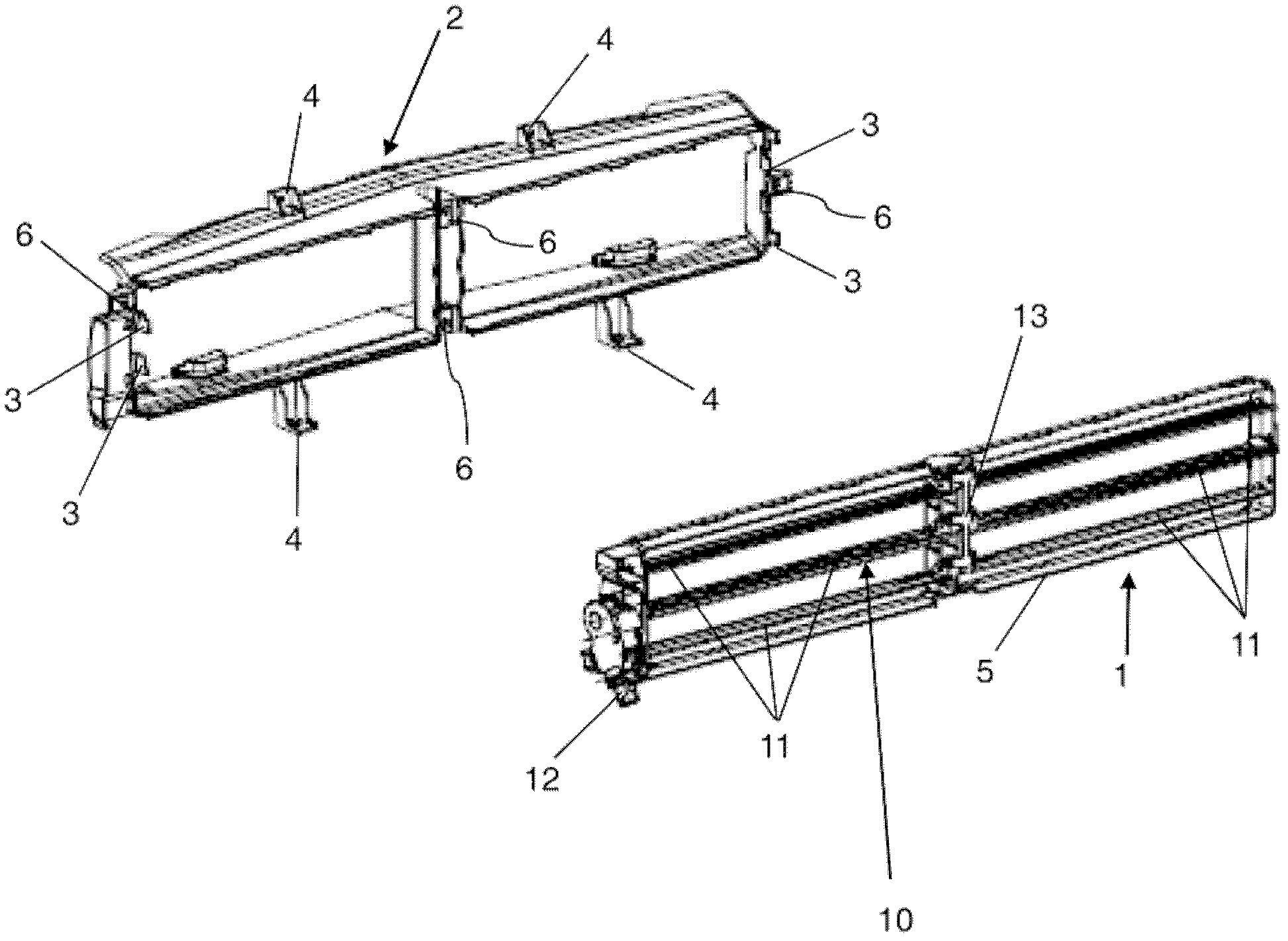
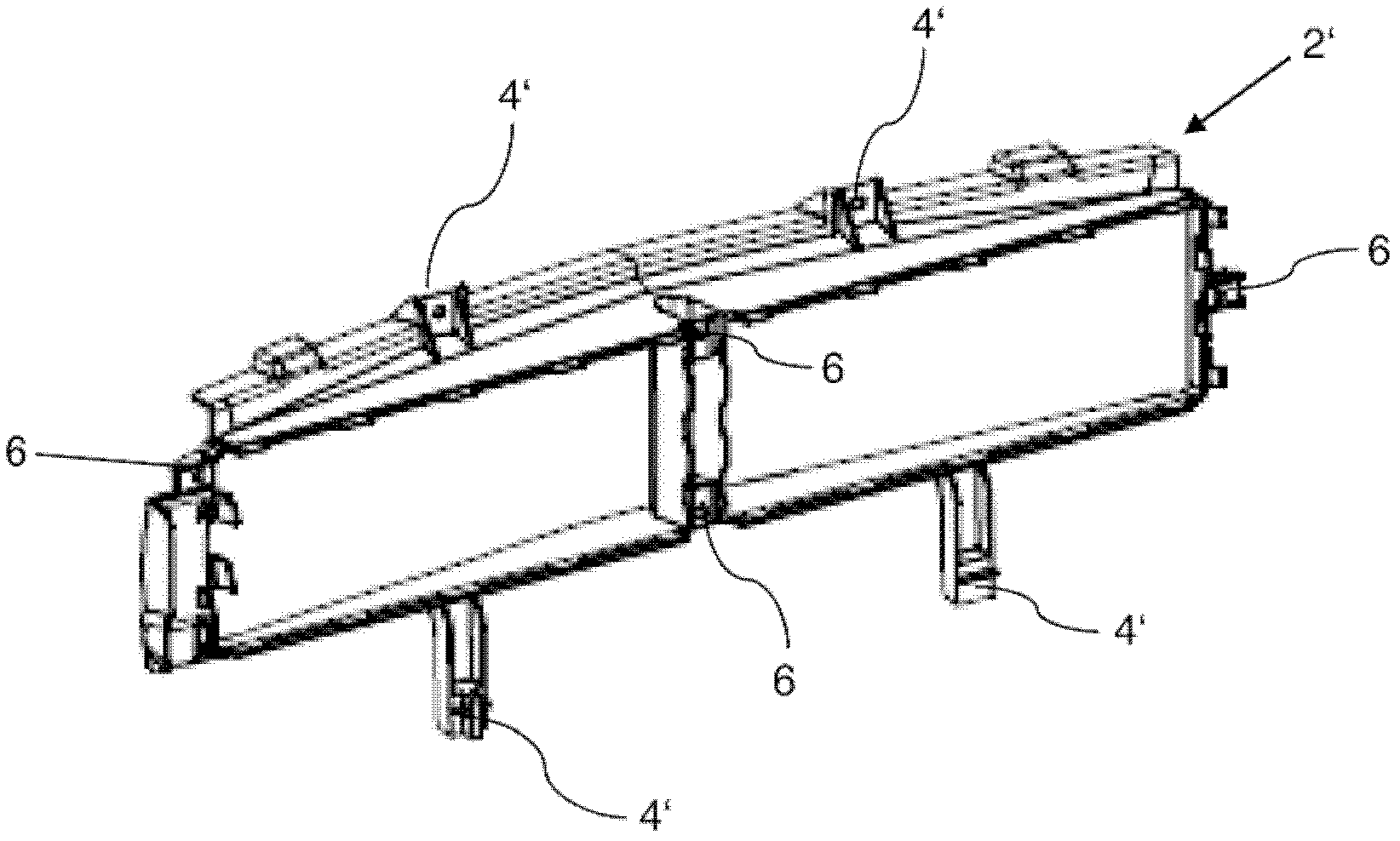
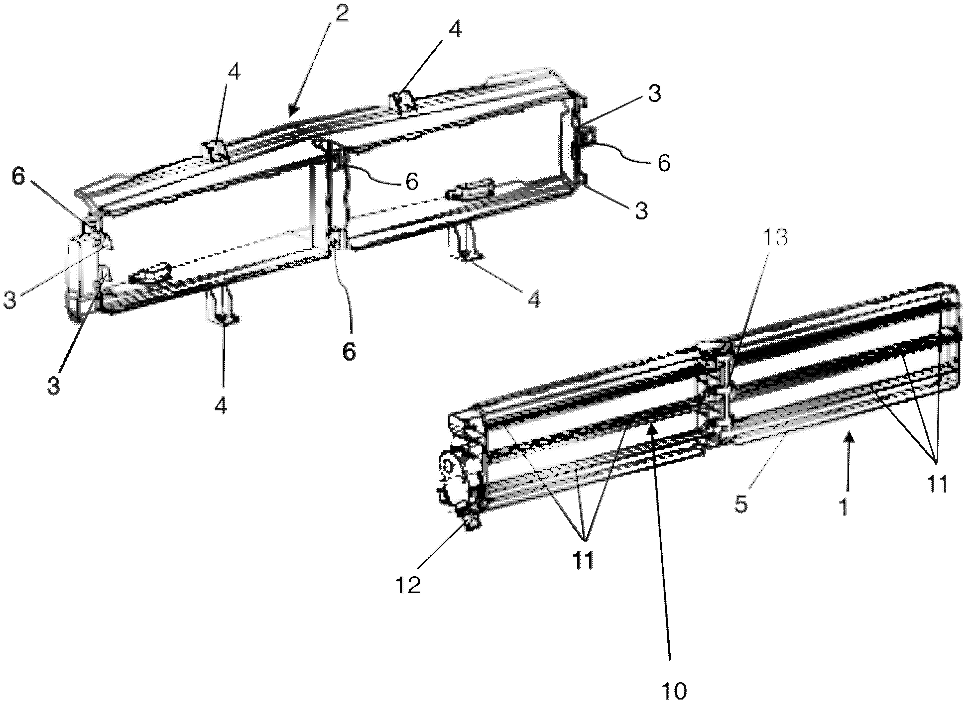
[0028] figure 1 A possible embodiment of a housing for a radiator shutter 10 of a motor vehicle (not shown) is shown in a schematic exploded view. The housing is designed in two parts and consists of a base part 1 and an adapter part 2 .

[0029] The base part 1 has a frame 5 on which a plurality of plate-shaped elements 11 of a radiator shutter 10 are rotatably mounted. These plate elements 11 are jointly rotatable by means of a drive 12 and a connecting rod 13 . For this purpose, the drive 12 is preferably arranged such that it directly drives one of the plate elements 11 and transmits the movement from one of the plate elements 11 to the remaining plate elements 11 via the connecting rod 13 . The throughflow opening formed by the frame 5 can be opened more or less by rotation of the plate element 11 so that in the mounted state of the radiator shutter 10 the cooling air flow inflow can be changed or adjusted by rotation of the plate element 11 . Driving wind in the engin...


PUM


Abstract

The present invention relates to a housing for the radiator blind (10) of a motor vehicle, which is provided with a base section (1) and an adapter section (2;2'), wherein the base section is used for accommodating the radiator blind (10); and the adapter section (2;2') is designed for being equipped on a preset connecting device.

Description

technical field [0001] The invention relates to a housing for a radiator shutter of a motor vehicle. The invention also relates to a radiator shutter and a motor vehicle. Background technique [0002] Cars usually use the driving wind to cool the engine. Adjustable cooling air louvers are generally used for this purpose, by means of which the cooling air flow through the engine compartment can be adjusted depending on the various operating states of the vehicle. In this case, the cooling air shutter is usually arranged between the coolant cooler and the fan of the vehicle. [0003] The installation space for radiator shutters that cars have today is very different. These different installation spaces necessitate an individual adaptation of the housings accommodating the radiator shutters. As more and more different car models are sold, manufacturers need to pre-machine a large number of different radiator shutter units at the same time. It's cumbersome and expensive. ...

Claims


Application Information

Patent Timeline
Patent Type & Authority Applications(China)
IPC IPC(8): B60K11/04
CPCB60K11/08B60K11/085Y02T10/88
Inventor V.伯恩特R.埃沃特
Owner GM GLOBAL TECH OPERATIONS LLC
Learn More