Device and method for controlling misfire of spark ignition engine

A spark ignition, engine technology, applied in automatic control, automatic control, electrical automatic control and other directions, can solve the problems of easy misdiagnosis, short service life, high price of in-cylinder pressure sensor, etc., to achieve accurate and reliable misfire diagnosis, Hazard minimization effect

Active Publication Date: 2012-04-18
TONGJI UNIV
View PDF6 Cites 25 Cited by
  • Summary
  • Abstract
  • Description
  • Claims
  • Application Information

AI Technical Summary

Problems solved by technology

[0008] However, this method is prone to misdiagnosis when the road conditions are bad, and requires an additional gravity acceleration sensor. In addition, this method can only be used within a certain range of engine operating conditions, especially at high speeds with small loads.
[0009] The most reliable way to judge misfire is to use the in-cylinder pressure sensor, but the price of the in-cylinder pressure sensor is extremely high, and it has strict requirements for installation and has a short service life
[0010] Oxygen sensors and exhaust pressure sensors can also be used to detect misfires, but they also have some disadvantages, such as high device costs, sluggish response, and inability to judge which cylinder is misfired
[0011] The existing technology only involves the method of detecting misfire, but does not mention what kind of real-time compensatory measures can be taken to prevent the damage caused by misfire in a timely and effective manner after misfire is detected

Method used


Image

  • Device and method for controlling misfire of spark ignition engine
  • Device and method for controlling misfire of spark ignition engine
  • Device and method for controlling misfire of spark ignition engine

Examples


Embodiment Construction

[0057] The present invention will be further described below with reference to the embodiments shown in the accompanying drawings.

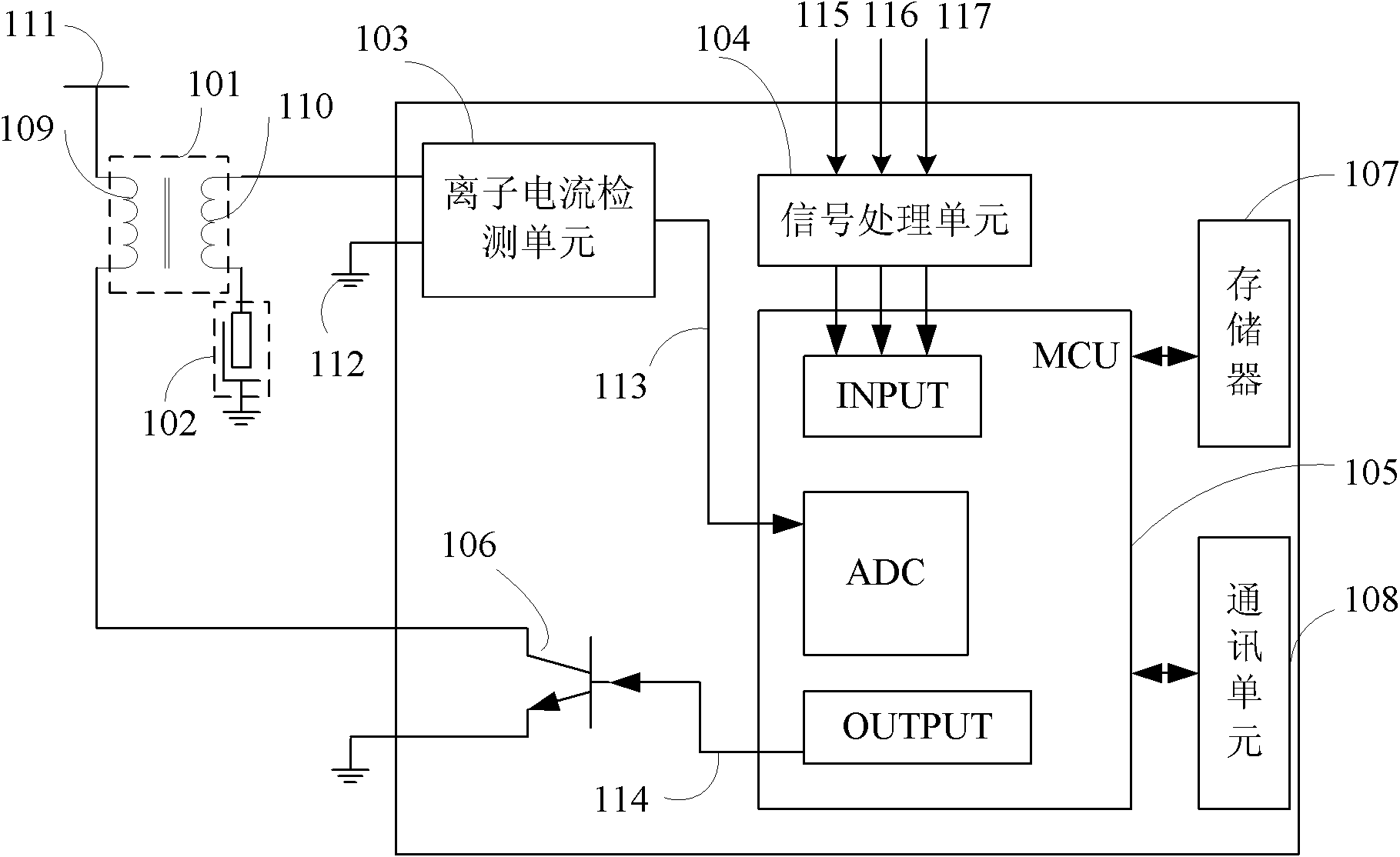
[0058] figure 1It is a schematic diagram of the device principle for spark ignition engine misfire control. The device comprises an ignition coil, a spark plug 102, an ion current detection unit 103, a signal processing unit 104, a micro control unit 105 and an ignition drive unit 106, and the ion current detection unit 103 is connected in series by the secondary coil 110 of the ignition coil, the spark plug In the circuit formed by 102 and ground 112, the ground can also be regarded as the engine block. The ion current signal 113 detected by the ion current detection unit 103 is input to the analog-to-digital conversion module ADC of the micro control unit 105 connected thereto. The engine working state signal enters the input module INPUT of the micro control unit 105 after being filtered, limited, shaped and buffered by the signal processing...


PUM


Abstract

The invention discloses a device for controlling the misfire of a spark ignition engine. The device comprises an ignition coil, a spark plug, an ionic current detection unit, a signal processing unit, a micro control unit and an ignition driving unit, wherein the ignition coil is used for providing an ignition power source to the spark plug; the spark plug is used for igniting in an air cylinder;the ionic current detection unit is used for detecting the ionic current of the ignition coil and sending the ionic current to the micro control unit; the signal processing unit is used for receivingan engine working state signal, processing the engine working state signal and then sending the processed engine working state signal to the micro control unit; the micro control unit is used for judging whether misfire happens or not according to the received ionic current and the engine working state signal; and the ignition driving unit is used for driving the ignition coil and controlling thespark plug to ignite if misfire exists. The invention also discloses a method for controlling the misfire of the spark ignition engine. According to the invention, the damage caused by misfire is minimized through misfire control.

Description

technical field [0001] The present invention relates to engine control technology, in particular to a method and device for detecting and controlling in-cylinder combustion of a spark-ignition engine. Background technique [0002] According to the definition of California Atmospheric Resources Bureau (CARB) regulations, engine misfire refers to the lack of ignition energy, too lean or too rich mixture, poor compression or other reasons that cause no combustion or poor combustion in the cylinder. [0003] When a misfire occurs, the average indicated pressure of the combustion process is greatly reduced, and the performance of the engine deteriorates. [0004] Studies have shown that a fire rate of about 2% would cause harmful emissions to exceed 1.5 times the emission standard limit. [0005] What's more serious is that the unburned mixture will burn after reaching the catalytic converter, which can easily cause damage to the catalytic converter. [0006] In order to avoid ...

Claims


Application Information

Patent Timeline
Patent Type & Authority Applications(China)
IPC IPC(8): F02P5/15
Inventor 李理光卞江范钱旺董光宇
Owner TONGJI UNIV
Why Eureka
Try Eureka