Temperature sensor

A temperature sensor and corresponding temperature technology, applied in thermometers, applications of thermometers, parts of thermometers, etc., can solve problems such as difficulty in improving heat dissipation, decrease in responsiveness of temperature sensors, and achieve suppression of heat dissipation effects, suppression of temperature changes, and high response sexual effect

Inactive Publication Date: 2012-04-18
NGK SPARK PLUG CO LTD
View PDF4 Cites 10 Cited by
  • Summary
  • Abstract
  • Description
  • Claims
  • Application Information

AI Technical Summary

Problems solved by technology

With the technologies described in Patent Documents 1 and 2, it is difficult to improve the problem of decreased responsiveness of the temperature sensor due to heat dissipation

Method used


Image

  • Temperature sensor
  • Temperature sensor
  • Temperature sensor

Examples


Embodiment Construction

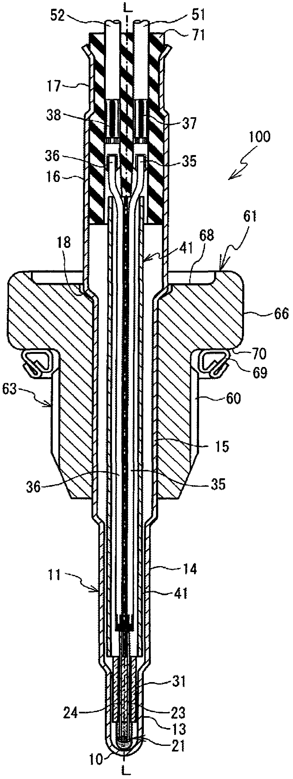
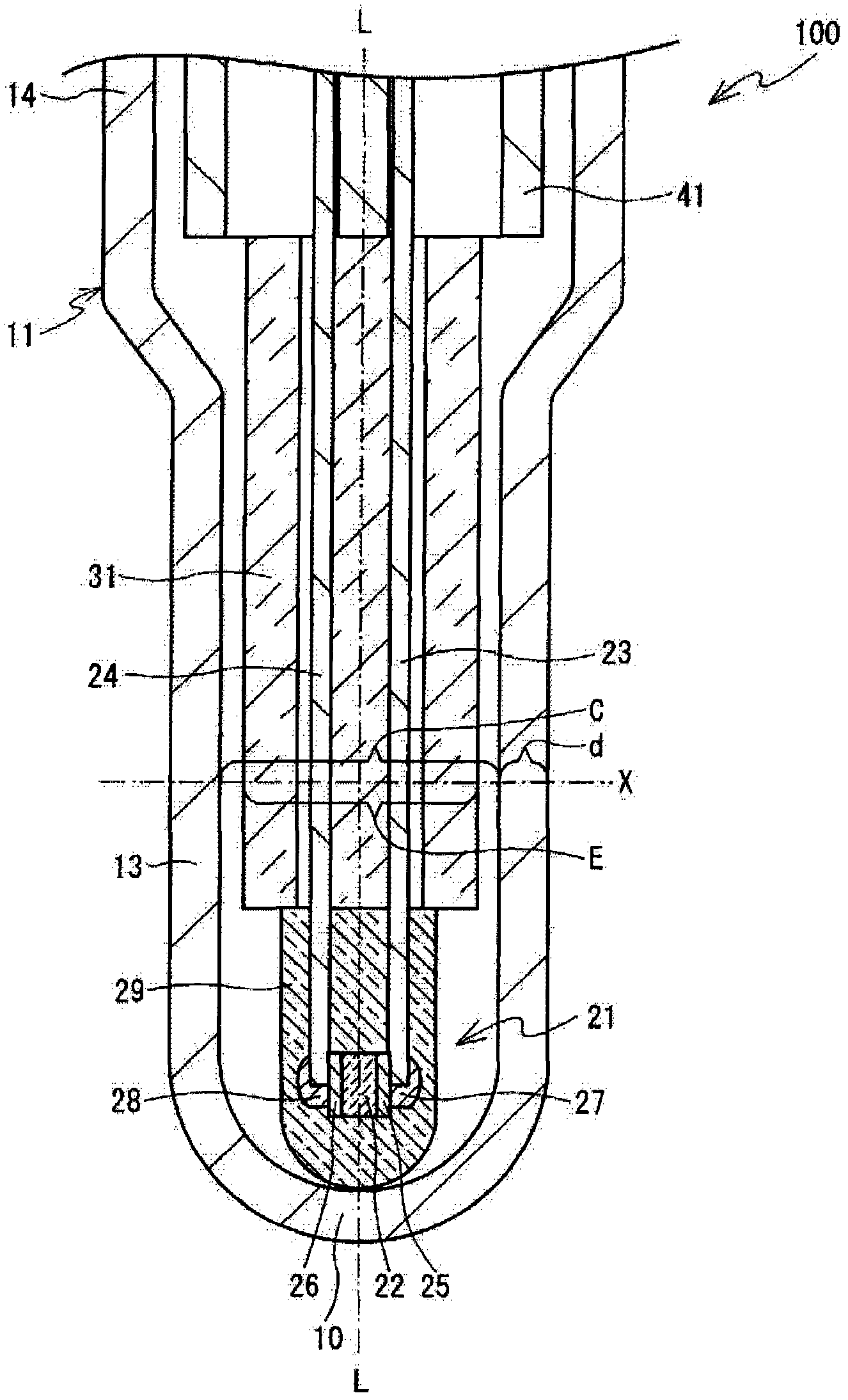
[0016] Hereinafter, a temperature sensor 100 as an embodiment embodying the present invention will be described with reference to the drawings. The attached drawings are used to explain the technical features that can be adopted in the present invention. The configurations of the described sensors are not limited thereto, and are merely illustrative examples. In the following instructions, start with figure 1 and figure 2 The up and down direction of the temperature sensor 100 is used as the up and down direction of the temperature sensor 100, with figure 1 and figure 2 The left-right direction of the temperature sensor 100 will be described as the left-right direction of the temperature sensor 100 . Will figure 1 and figure 2 The front side of the drawing and the deep side of the drawing will be described as the front side and the rear side of the temperature sensor 100, respectively. by figure 1 and figure 2 above as the rear end side of the temperature sensor 1...


PUM

PropertyMeasurementUnit
diameteraaaaaaaaaa
thicknessaaaaaaaaaa

Abstract

A temperature sensor (100) includes a heat-sensitive element (21) having a thermistor sintered-body (22), an insulating support (31), an insulation sheath (41) and a housing tube (11). The insulating support (31) is in contact with the rear end of the heat-sensitive element (21) and the insulation sheath (41) is in contact with the rear end of the insulating support (31). The housing tube (11) accommodates the heat-sensitive element (21), the insulating support (31) and the insulation sheath (41). The housing tube (11) includes a sheath accommodation portion (14) which accommodates the insulation sheath (41) and a distal accommodation portion (13). The distal accommodation portion (13) is located toward the distal end of the housing tube (11) with respect to the sheath accommodation portion (14), is smaller in outside diameter than the sheath accommodation portion (14), and accommodates at least half of the insulating support (31) as measured from the axially distal end of the insulating support (31).

Description

technical field [0001] The present invention relates to a temperature sensor used for detecting the temperature of measurement target fluids such as exhaust gas and intake gas. Background technique [0002] Conventionally, a temperature sensor having a thermosensitive portion whose electrical characteristics change according to temperature is known. The temperature sensor is attached to, for example, an exhaust pipe of an engine of an automobile, and measures the temperature of exhaust gas flowing through the exhaust pipe. For the thermosensitive part of the temperature sensor, for example, a thermistor sintered body is used, and its resistance value changes according to temperature. A pair of electrodes for detecting the resistance value of the thermosensitive part is arranged to sandwich the thermosensitive part. The thermosensitive part and the pair of electrodes are sealed by a sealing part made of glass or the like, thereby forming a thermosensitive element. The rear...

Claims


Application Information

Patent Timeline
Patent Type & Authority Applications(China)
IPC IPC(8): G01K7/22
CPCG01K1/16G01K2205/04G01K7/16G01K1/08
Inventor 伊藤政伦松尾康司石川聪
Owner NGK SPARK PLUG CO LTD
Why Eureka
Try Eureka