A device for monitoring condition of a railway supply

A railway and state-of-the-art technology, applied in the direction of railway vehicles, collectors, electric vehicles, etc., can solve problems such as the inability to use pantographs

Inactive Publication Date: 2012-04-18
ALSTOM TRANSPORT SA
View PDF4 Cites 3 Cited by
  • Summary
  • Abstract
  • Description
  • Claims
  • Application Information

AI Technical Summary

Problems solved by technology

[0004] Because the measuring element is placed between the pantograph and the power line, the pantograph cannot be used during commercial service due to safety concerns, in particular due to the risk of electric shock

Method used


Image

  • A device for monitoring condition of a railway supply
  • A device for monitoring condition of a railway supply
  • A device for monitoring condition of a railway supply

Examples


Embodiment Construction

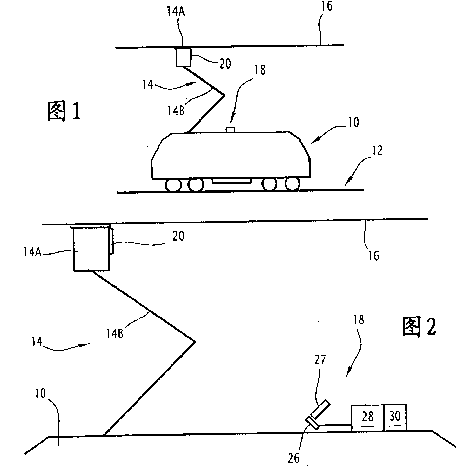
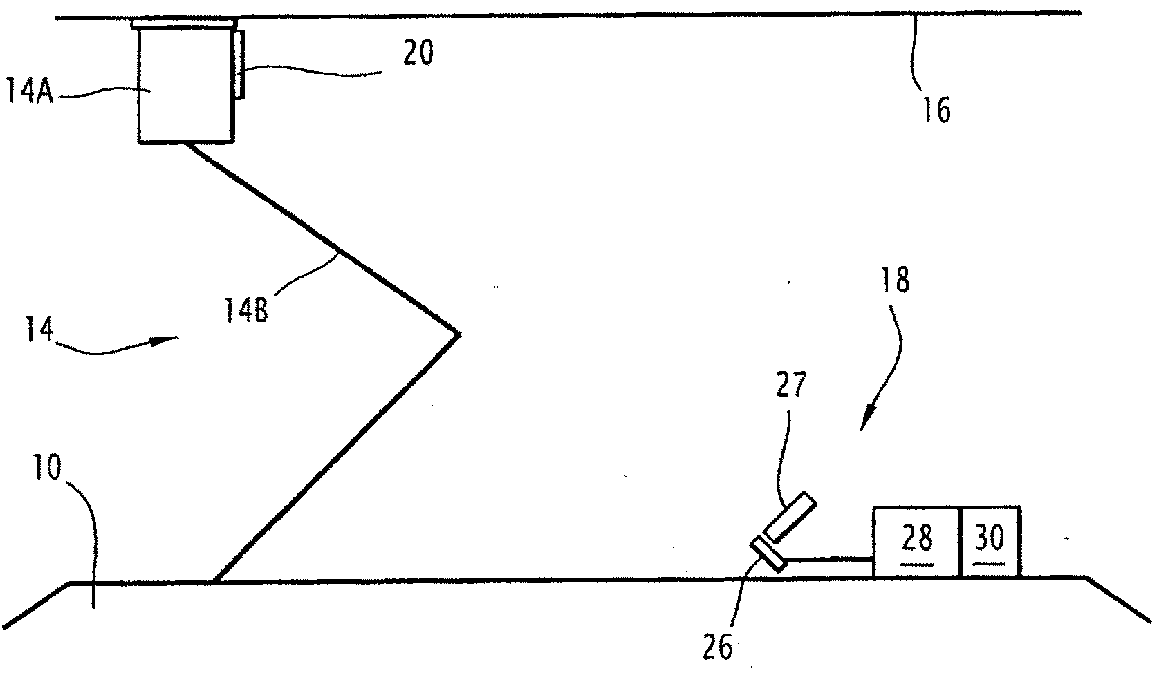
[0023] refer to figure 1 , depicts a vehicle 10 for operation on a railroad 12 .

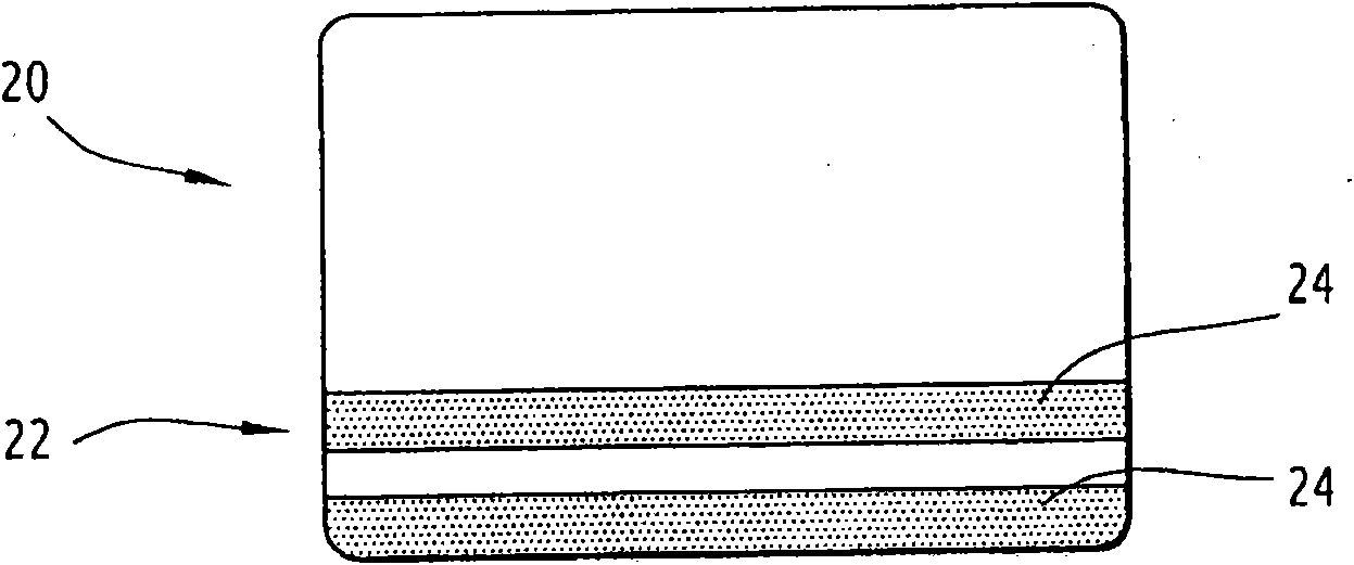
[0024] Vehicle 10 is an electric train that includes at least one pantograph 14 for collecting electrical current from a power line 16 (also referred to as a catenary 16 ) of railroad 12 to power electric train 10 . For this purpose, the pantograph 14 comprises a pantograph head 14A intended to come into contact with and slide along the power line 16 . The pantograph 14 also includes an articulating rod 14B for supporting the pantograph head 14A. The articulating rod 14B acts as a spring for pressing the pantograph head 14A against the power line 16 .

[0025] For maintenance reasons, and in particular to detect defects in the power line 16 , it is important to monitor parameters indicative of the operational capability of said power line 16 . The parameter currently monitored is the force exerted by the pantograph 14 on the power line 16, which parameter can be deduced from the movement of t...


PUM


Abstract

The device (18) is intended to monitor condition of a railway supply line when the supply line is in contact with a head (14A) of a pantograph (14) of a vehicle (10) in order to power said vehicle (10). The device (18) includes a camera (26) for monitoring parameters indicative of operating capability of said supply line. The device (18) includes a reflective element (20), comprising a pattern (22), intended to be arranged onto the pantograph head (14A). The camera (26) is intended to be arranged on the vehicle (10) so as to register the pattern position regarding a vertical direction.

Description

technical field [0001] The present invention relates to a device for monitoring the condition of a railway power line (also known as catenary or overhead line) as it comes into contact with the pantograph head of a vehicle to power the vehicle. Background technique [0002] A device for monitoring the condition of railway power lines is known from the prior art, in particular JP 2001-235310. The apparatus includes a camera for monitoring a parameter indicative of the operational capability of said transmission line. [0003] In JP2001-235310, a vehicle includes a pantograph with a measuring element, the pantograph including a bracket and a sliding contact for sliding along a power line. The sliding contact is connected to the bracket by a spring. The sliding contact and the bracket respectively support the infrared light source, so that the camera is used to record the relative position of the light source with respect to the vertical direction. [0004] Since the measuri...

Claims


Application Information

Patent Timeline
Patent Type & Authority Applications(China)
IPC IPC(8): G01N21/88G01R31/08B60M1/28
CPCB60L5/26B60M1/28B60L2200/26
Inventor F·塔纳罗玛奎兹P·格拉塔科斯玛蒂F·J·桑切兹普加达斯J·R·吉梅内兹敏古尔J·安坦斯E·萨拉爱斯特瓦
Owner ALSTOM TRANSPORT SA
Why Eureka
Try Eureka