
Monitoring system for testing yaw driving cabinet

A monitoring system and drive cabinet technology, which is applied in power supply testing, testing circuits, and testing dielectric strength, etc., can solve problems such as safety accidents caused by operational errors, affecting test efficiency, and easy to neglect power supply status, so as to improve safety and reliability Effect

Pending Publication Date: 2020-09-18
天津瑞源电气有限公司
View PDF0 Cites 0 Cited by
  • Summary
  • Abstract
  • Description
  • Claims
  • Application Information

AI Technical Summary

Problems solved by technology

[0003] In the field of wind power automation, there are problems such as frequent power-on and power-off operations on the power input side and continuous use of multimeters for power monitoring during product factory testing, which greatly affects test efficiency and one-sidedness in power monitoring. The power input has AC 400V and DC 24V, and the power supply has long-term power supply and intermittent power supply during debugging. Therefore, it is easy to neglect the power supply status during the test process, resulting in safety accidents due to operation errors, and there are potential safety hazards
For the yaw drive cabinet, the stability of the power supply on the input side has a great influence on the test, such as voltage, current, frequency, etc. For the test on the load side, in many cases, the motor load test is not performed, so it cannot pass The data can accurately judge the impact of the yaw drive cabinet on the load side, and cannot provide data reference for later product optimization

Method used


Image

  • Monitoring system for testing yaw driving cabinet
  • Monitoring system for testing yaw driving cabinet
  • Monitoring system for testing yaw driving cabinet

Examples


Embodiment Construction

[0028] It should be noted that the embodiments of the present invention and the features in the embodiments can be combined with each other if there is no conflict.

[0029] In the description of the present invention, it should be noted that the terms "installation", "connected" and "connected" should be understood in a broad sense, unless otherwise clearly specified and limited. For example, they can be fixed or detachable. Connected or integrally connected; it can be a mechanical connection or an electrical connection; it can be directly connected or indirectly connected through an intermediate medium, and it can be the internal communication between two components. For those of ordinary skill in the art, the specific meaning of the above-mentioned terms in the present invention can be understood through specific situations.

[0030] Hereinafter, the present invention will be described in detail with reference to the drawings and in conjunction with the embodiments.

[0031] This...


PUM


Abstract

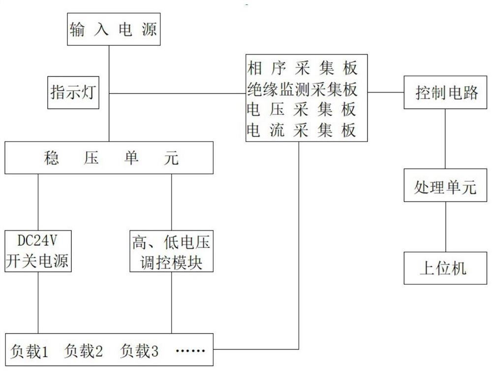
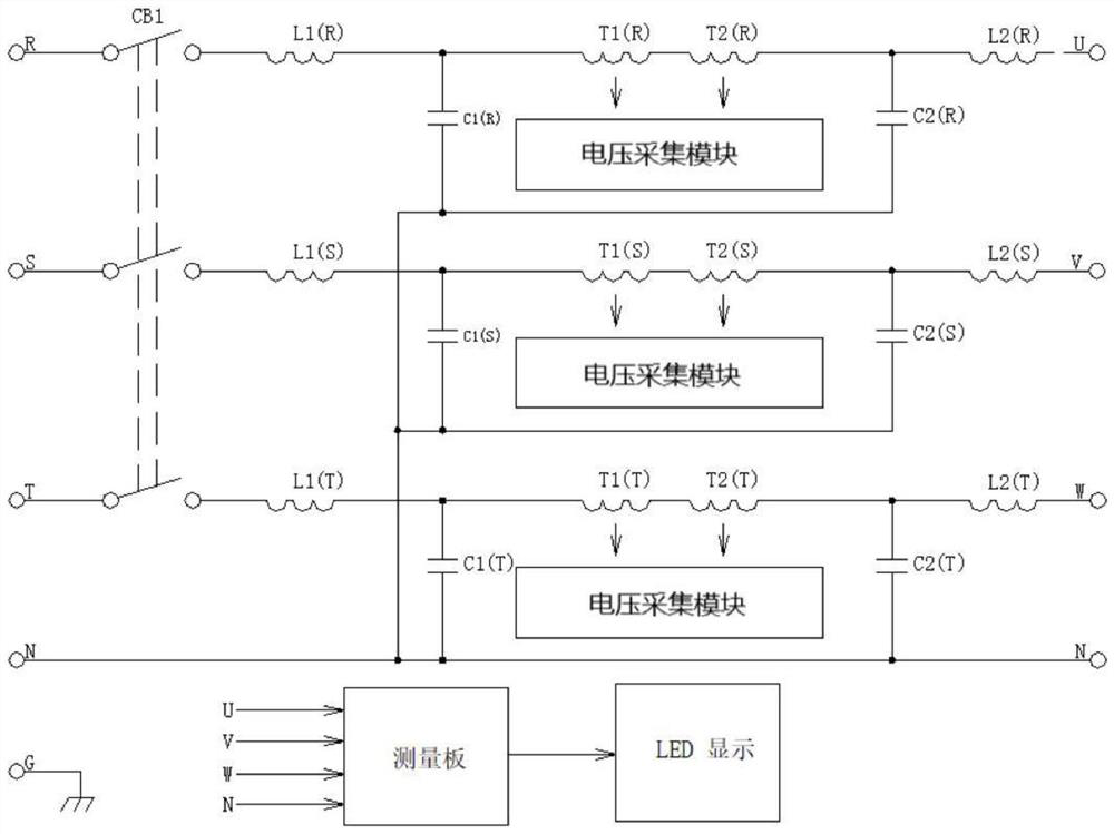
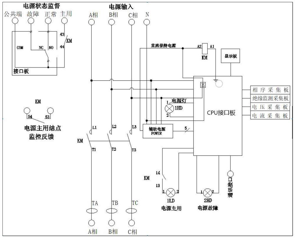
The invention provides a monitoring system for testing a yaw driving cabinet. The monitoring system comprises an input power supply, a voltage stabilizing unit and a processing unit. The input power supply is connected with the voltage stabilizing unit, and the voltage stabilizing unit supplies power to the monitoring system. The voltage stabilizing unit is also connected with a DC 24V module anda high-low voltage regulation and control module for supplying power to different loads. The load is connected with a plurality of acquisition modules, and the acquisition modules are connected with the processing unit through a control circuit. The acquisition modules are used for monitoring phase sequence, voltage, current and frequency information of an input power supply end and a load side, and have insulation monitoring and phase failure and stagger protection alarm functions. The processing unit is connected with an upper computer. According to the monitoring system for testing a yaw driving cabinet, testing equipment is integrated, meanwhile, a stable power supply is provided for testing, the situation that a universal meter and other detection equipment are manually used for monitoring the state of the power supply is reduced, fluctuation and the insulation state of a power grid can be monitored, and the safety and reliability are improved.

Description

Technical field [0001] The invention belongs to the field of wind power automation industry, and particularly relates to a monitoring system for yaw drive cabinet testing. Background technique [0002] The yaw drive cabinet of the wind turbine generator includes a controller, a rectifier unit and an inverter unit. One yaw controller can be used to control multiple yaw inverter units, and each yaw inverter unit drives one or more yaw Aeromotor to achieve yaw movement. [0003] In the field of wind power automation, there are problems such as frequent power-on and power-off operations on the power input side and constant use of a multimeter for power monitoring during product factory testing, which greatly affects the test efficiency and is partial to power monitoring. The power input has AC 400V. And DC 24V two kinds, and the power supply has long-term power supply and intermittent power supply during debugging. Therefore, it is easy to neglect the power supply state during the tes...

Claims


Application Information

Patent Timeline
Patent Type & Authority Applications(China)
IPC IPC(8): G01R31/42G01R31/00G01R31/40G01R31/14G01R29/18G01R21/00G01R21/06G01R19/00G05F1/12G01K1/14
CPCG01K1/14G01R19/00G01R21/00G01R21/06G01R29/18G01R31/00G01R31/14G01R31/40G01R31/42G05F1/12
Inventor 董世捷杨康
Owner 天津瑞源电气有限公司
Learn More