Piezoelectric ceramic driving power supply and driving method

A piezoelectric ceramic drive, piezoelectric ceramic technology, applied in the direction of generators/motors, piezoelectric effect/electrostrictive or magnetostrictive motors, electrical components, etc., can solve the problems of low linear control accuracy and hysteresis , to achieve the effect of improving linear control accuracy and eliminating hysteresis

Inactive Publication Date: 2012-04-18
SUZHOU UNIV
View PDF3 Cites 18 Cited by
  • Summary
  • Abstract
  • Description
  • Claims
  • Application Information

AI Technical Summary

Problems solved by technology

[0004] In order to solve the above technical problems, the embodiment of the present application provides a piezoelectric ceramic driving power supply and a driving method to solve the problems of low linear control accuracy and hysteresis in the existing piezoelectric ceramic driving power supply. The technical solution is as follows:

Method used


Image

  • Piezoelectric ceramic driving power supply and driving method
  • Piezoelectric ceramic driving power supply and driving method
  • Piezoelectric ceramic driving power supply and driving method

Examples


Embodiment Construction

[0039] In order to enable those skilled in the art to better understand the technical solutions in the present application, the technical solutions in the embodiments of the present application will be clearly and completely described below in conjunction with the drawings in the embodiments of the present application. Obviously, the described The embodiments are only some of the embodiments of the present application, but not all of them. Based on the embodiments in this application, all other embodiments obtained by persons of ordinary skill in the art without creative efforts shall fall within the protection scope of this application.

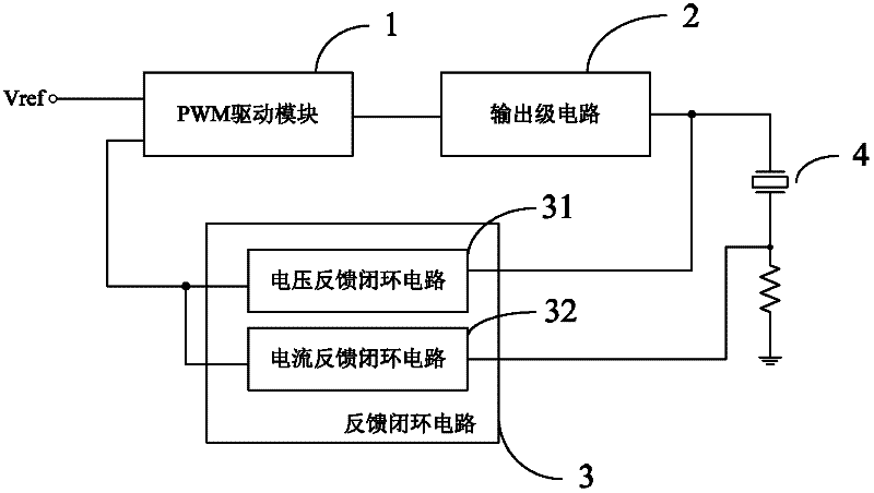
[0040] See figure 1 , shows a functional block diagram of a piezoelectric ceramic drive power supply provided by the embodiment of the present application.

[0041] The piezoelectric ceramic drive power supply includes: a PWM drive module 1, an output stage circuit 2, and a feedback closed-loop circuit 3, wherein:

[0042] The PWM drive mo...


PUM


Abstract

The invention discloses a piezoelectric ceramic driving power supply and a driving method. The piezoelectric ceramic driving power supply comprises a pulse width modulation (PWM) driving module, an output stage circuit and a feedback closed loop circuit, wherein the feedback closed loop circuit comprises a voltage feedback closed loop circuit and a current feedback closed loop circuit. The displacement of piezoelectric ceramics and the quantity of electric charges on the piezoelectric ceramics are in linear relation, namely the displacement of the piezoelectric ceramics and current flowing through the piezoelectric ceramics are in the linear relation; however, the displacement of the piezoelectric ceramics and voltage on the piezoelectric ceramics are in nonlinear relation. In the piezoelectric ceramic driving power supply and the driving method in the embodiment of the invention, the current feedback closed loop circuit is arranged, and the voltage feedback closed loop circuit and the current feedback closed loop circuit control a voltage signal output by the piezoelectric ceramic driving power supply according to a voltage signal and a current signal on the piezoelectric ceramics, thereby avoiding hysteresis and improving linear control accuracy.

Description

technical field [0001] The present application relates to the field of driving power technology, in particular to a piezoelectric ceramic driving power and a driving method. Background technique [0002] With the development of science and technology and the continuous expansion of research fields, the application requirements of nano-positioning systems are becoming more and more extensive. As a new type of material in the field of nano-level positioning, piezoelectric ceramics have small volume, high displacement resolution, high frequency response, and no noise. , no heat and other characteristics, it is an ideal micro-displacement element, the piezoelectric ceramic driving power supply is the driving part of the piezoelectric ceramic, and it is also the core part of the piezoelectric ceramic. [0003] Through the research on the prior art, the inventors found that the conventional pulse width modulation driving power supply is based on the voltage feedback linear control...

Claims


Application Information

Patent Timeline
Patent Type & Authority Applications(China)
IPC IPC(8): H02N2/06H02M3/158
Inventor 汝长海杜志博王澄刘吉柱
Owner SUZHOU UNIV
Why Eureka
Try Eureka