Supercharge Your Innovation With Domain-Expert AI Agents!

motor control unit

A motor control and circuit technology, used in AC motor control, current controller, electronic commutation motor control, etc., can solve problems such as increased noise level

Active Publication Date: 2014-10-15
KK TOSHIBA
View PDF6 Cites 0 Cited by
  • Summary
  • Abstract
  • Description
  • Claims
  • Application Information

AI Technical Summary

Problems solved by technology

Since the torque fluctuates due to the current change at this time, there is a problem that the level of noise generated when the motor is driven increases.

Method used


Image

  • motor control unit
  • motor control unit
  • motor control unit

Examples


Embodiment Construction

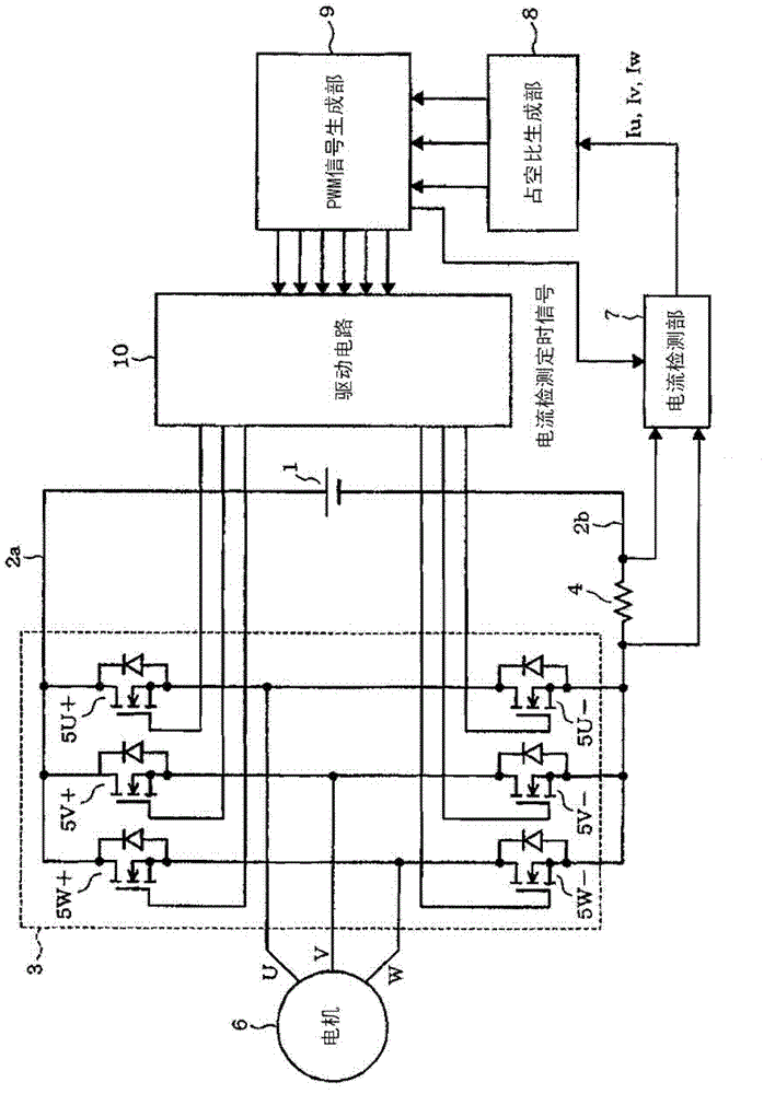
[0029] Refer below Figure 1 to Figure 11 The first embodiment will be described. figure 1 It is a functional block diagram showing the configuration of the motor control device. The DC power supply unit 1 is represented by a symbol of a DC power supply, but includes a rectification circuit and / or a smoothing capacitor when the DC power is generated from a commercial AC power supply. DC power supply unit 1 is connected to converter circuit (DC / AC converter) 3 via positive side bus 2 a and negative side bus 2 b , but shunt resistor 4 as a current detection element is inserted on the side of negative side bus 2 b . The converter circuit 3 is composed of, for example, N-channel type power MOSFETs 5 (U+, V+, W+, U-, V-, W-) connected to a three-phase bridge, and the output terminals of each phase are connected to a motor composed of, for example, a brushless DC motor. The coils of each phase of 6 are connected respectively.

[0030] The terminal voltage (signal corresponding t...


PUM


Abstract

A motor control device according to one embodiment of the present invention includes: an inverter circuit composed of a plurality of switching elements connected to a three-phase bridge, and drives the motor by converting direct current into three-phase alternating current; The DC side is connected and generates a signal corresponding to the current value; the PWM signal generation unit determines the rotor position according to the phase current of the above-mentioned motor, and generates a three-phase PWM signal pattern to track the above-mentioned rotor position; the current detection unit, according to the above-mentioned The signal generated by the current detection element and the above-mentioned PWM signal pattern are used to detect the phase current of the above-mentioned motor, and the above-mentioned PWM signal generation unit generates the above-mentioned three-phase PWM signal pattern, so that the above-mentioned current detection unit can be within the carrier period of the above-mentioned PWM signal. The current values ​​of the two phases are detected at two fixed timings.

Description

[0001] This application is based on and claims priority from prior Japanese Patent Application No. 2010-215246 filed on September 27, 2010, the entire contents of which are incorporated herein by reference. technical field [0002] Embodiments of the present invention relate to a motor control device that detects a phase current by a current detection element disposed in a DC portion of an inverter circuit. Background technique [0003] Conventionally, when detecting currents of U, V, and W phases for controlling a motor, current detection is performed using a single shunt resistor inserted in a DC portion of an inverter circuit. [0004] In this way, in order to detect all three-phase currents, within one period of a PWM (Pulse Width Modulation) carrier, a three-phase PWM signal pattern needs to be generated to detect more than two phases of current. For example, as shown in Figure 18 (making the carrier wave a sawtooth wave), when the duty ratios of the U and V phases are ...

Claims


Application Information

Patent Timeline
Patent Type & Authority Patents(China)
IPC IPC(8): H02P27/08H02P6/18H02M1/00H02P6/06H02P6/08H02P6/16H02P6/182H02P6/28
CPCH02M7/5395H02M2001/0009H02P27/08H02P6/18H02M1/0009
Inventor 前川佐理
Owner KK TOSHIBA
Features
  • R&D
  • Intellectual Property
  • Life Sciences
  • Materials
  • Tech Scout
  • Unparalleled Data Quality
  • Higher Quality Content
  • 60% Fewer Hallucinations
Learn More