Comparator

A comparator and output terminal technology, applied in the field of comparators, can solve the problems of long delay time of comparators, achieve the effect of shortening delay time and improving flipping speed

Active Publication Date: 2012-04-18
WUXI ZGMICRO ELECTRONICS CO LTD
View PDF3 Cites 12 Cited by
  • Summary
  • Abstract
  • Description
  • Claims
  • Application Information

AI Technical Summary

Problems solved by technology

In low-power applications, if the tail current of the differential input pair is small, this period will be longer, resulting in a longer delay time of the comparator, which is not desirable for most applications

Method used


Image

  • Comparator
  • Comparator
  • Comparator

Examples


Embodiment Construction

[0026]In order to make the above objects, features and advantages of the present invention more comprehensible, the present invention will be further described in detail below in conjunction with the accompanying drawings and specific embodiments. Words related to electrical connection such as "connected", "connected to" and "connected to" herein may indicate direct or indirect electrical connection.

[0027] Reference herein to "one embodiment" or "an embodiment" refers to a particular feature, structure or characteristic that can be included in at least one implementation of the present invention. "In one embodiment" appearing in different places in this specification does not all refer to the same embodiment, nor is it a separate or selective embodiment that is mutually exclusive with other embodiments.

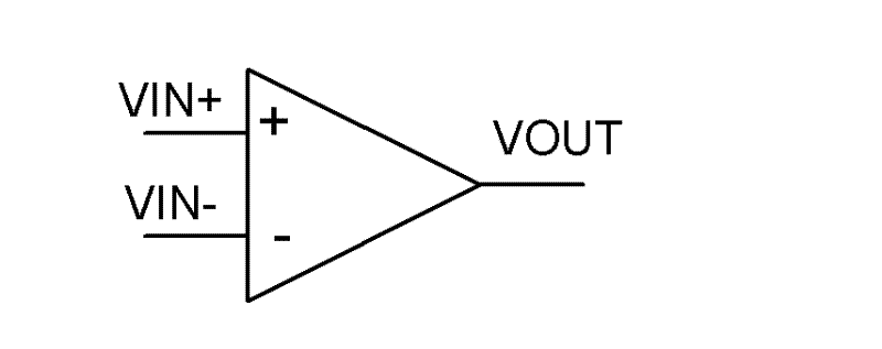
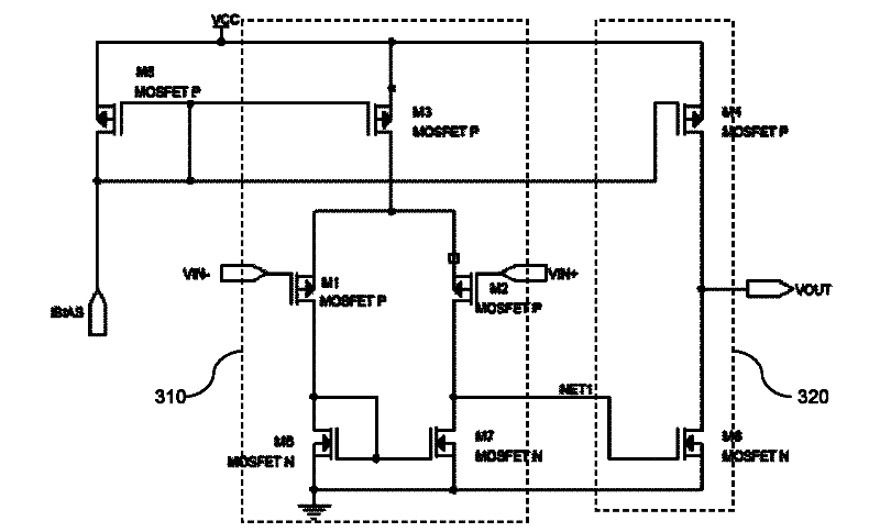
[0028] The invention provides a comparator, which includes an input stage circuit and an output stage circuit. The input stage circuit includes a first input terminal, a ...


PUM


Abstract

The invention provides a comparator. The comparator comprises an input-stage circuit, an output-stage circuit and a clamping circuit, wherein the input-stage circuit comprises a first input end, a second input end and an output end; and when the voltage of the first input end equals to the voltage of the second input end, the voltage at the output end is flipped; the output-stage circuit comprises an input end and an output end, wherein the input end of the output-stage circuit is connected with the output end of the input-stage circuit; when the voltage at the output end of the input-stage circuit is flipped, the voltage at the output end of the output-stage circuit is also flipped; the clamping circuit is connected between the output end of the input-stage circuit and the output end of the output-stage circuit and is used for clamping the lowest value of the voltage of the output end of the input-stage circuit at a first voltage threshold value and clamping the highest value of the voltage of the output end of the input-stage circuit at a second voltage threshold value. By using the comparator, the delay time of the comparator can be shortened, so that the flipping speed of the comparator is improved.

Description

【Technical field】 [0001] The invention relates to the field of circuit design, in particular to a comparator. 【Background technique】 [0002] A comparator is a circuit module commonly used in integrated circuits. Its function is to compare the signal difference at the input terminal and output a discrete high or low signal. Please refer to figure 1 As shown, it is a structural block diagram of a comparator in the prior art, and the comparator includes a non-inverting input terminal VIN+, an inverting input terminal VIN- and an output terminal VOUT. Please refer to figure 2 shown, which is figure 1 The ideal transmission curve of the comparator is shown, where the abscissa is VIN+-VIN-, the ordinate is the output signal VOUT, VOH is the high-level signal value of the output signal VOUT, and VOL is the low-level signal of the output signal VOUT value. When the positive phase input voltage VIN+ is greater than the negative phase input voltage VIN-, the comparator output s...

Claims


Application Information

Patent Timeline
Patent Type & Authority Applications(China)
IPC IPC(8): H03K5/24
Inventor 杨喆王钊
Owner WUXI ZGMICRO ELECTRONICS CO LTD
Why Eureka
Try Eureka