Roller wheel for track belt-type traveling vehicle

A crawler type and vehicle technology, which is applied in the field of runners of crawler type vehicles, can solve the problems of easy deformation and uneven contact of the inner circumference of the roller sleeve.

Inactive Publication Date: 2012-04-18
KOMATSU LTD
View PDF8 Cites 6 Cited by
  • Summary
  • Abstract
  • Description
  • Claims
  • Application Information

AI Technical Summary

Problems solved by technology

[0007] However, if the coupling rings are pressed into the outer peripheries of the left and right roll sleeves, the portions of the roll sleeves where the coupling rings are pressed are deformed toward the inner peripheral side, and as a result, the inner peripheral portions of the roll sleeves are easily deformed.
The inner peripheral portion of the sleeve is rotatably supported on the shaft by the bushing, however, if a part of the inner peripheral portion of the sleeve is deformed toward the inner peripheral side, uneven contact will occur between the bushing and the shaft )

Method used


Image

  • Roller wheel for track belt-type traveling vehicle
  • Roller wheel for track belt-type traveling vehicle
  • Roller wheel for track belt-type traveling vehicle

Examples


no. 1 example

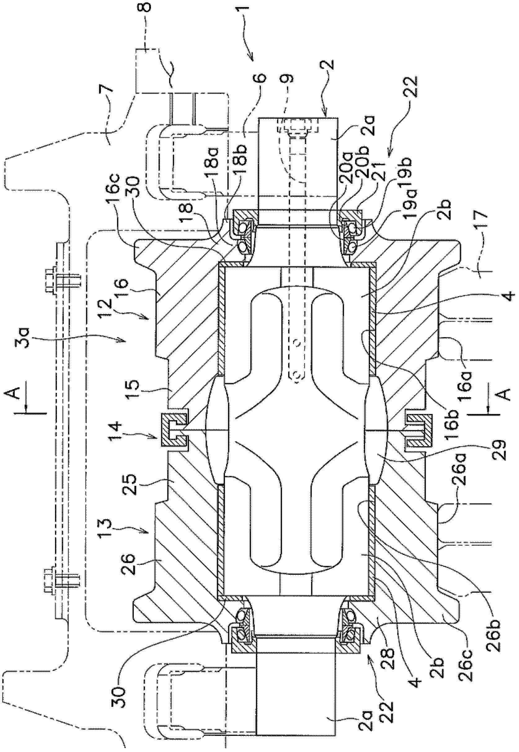
[0070] figure 1 It is a longitudinal sectional view of the running wheel of the crawler-type traveling vehicle according to the first embodiment of the present invention. The runner 1 is provided on the non-contact surface side of the crawler belt, and has a shaft 2, a roller assembly 3a, and two bushes 4 as bearings.

[0071] [axis]

[0072] The shaft 2 has a small-diameter support portion 2a at both ends, ie, an inner end and an outer end, and has two bearing mounting portions 2b having a larger diameter than the support portion 2a at a central portion where the roller assembly 3a is provided. Here, "inside" refers to the side close to the vehicle body frame 8, that is, figure 1 In the right side, "outside" refers to the side away from the vehicle body frame 8 that is figure 1 in the left side. The supporting parts 2a are respectively supported on the large steering members 7 (big boggies) via the small steering members (small boggies) 6 . Furthermore, the large stee...

no. 2 example

[0103] [structure]

[0104] Figure 9 A runner 40 showing a second embodiment of the present invention is shown. The runner 40 of the second embodiment differs from the first embodiment only in the inner roller sleeve, outer roller sleeve, and coupling ring constituting the roller assembly, and the other structures are the same as in the first embodiment. Only the parts different from the first embodiment will be described here.

[0105] The roller assembly 3b is the same as the first embodiment, and has an inner roller sleeve 42 arranged on the inner side close to the vehicle body frame, an outer roller sleeve 43 arranged on the outer side of the inner roller sleeve 42, and is used to combine the two rollers. The coupling ring 44 of the sleeve 42,43.

[0106] The inner sleeve 42 is formed in a cylindrical shape, and has an inner joining portion 45 and an inner tread portion 46 from the outer side toward the inner side.

[0107] As enlarged Figure 10 As shown, the inner ...

no. 3 example

[0122] Figure 14 A longitudinal sectional view showing a running wheel of a crawler-type traveling vehicle according to a third embodiment of the present invention. This runner 101 is provided on the non-contact surface side of the track, and has a shaft 102, a roller assembly 103a, and two bushes 104 as bearings.

[0123] [axis]

[0124] The shaft 102 has a small-diameter support portion 102a at both ends, ie, an inner end and an outer end, and has two bearing mounting portions 102b having a larger diameter than the support portion 102a at a portion where the roller assembly 103a is provided. The supporting parts 102a are respectively supported on the large steering members 107 via the small steering members 106 . Also, a large steering member 107 is fixed to a vehicle body frame 108 . Thus, axle 102 is supported on vehicle body frame 108 . Furthermore, the shaft 102 is formed with an oil supply hole 109 extending from one end on the inside toward the outside and communi...


PUM


Abstract

A roller wheel for a track belt-type traveling vehicle, configured in such a manner that uneven contact between a roller including a bearing, such as a bush, and a shaft is minimized. A roller wheel for a track belt-type traveling vehicle, comprising a shaft (2), a roller assembly (3a) disposed on the outer periphery of the shaft (2), and a bush (4) for rotatably supporting the roller assembly (3a) on the shaft (2). The roller assembly (3a) is provided with an inner roller shell (12), an outer roller shell (13), and a joining ring (14). The inner roller shell (12) is disposed on the inner side close to a vehicle frame (8) and has in the outer peripheral section at the outer end thereof an annular groove (15a) having a ridge (15b) located in the inside thereof. The outer roller shell (13) is disposed outside the inner roller shell (12) and has an annular groove (25a) having a ridge (25b) in the inside thereof. The joining ring (14) engages with both the ridges (15b, 25b) of the annularrings (15a, 25a) to join the roller shells (12, 13) together.

Description

technical field [0001] The invention relates to a running wheel of a crawler-type traveling vehicle, in particular to a running wheel of a crawler-type traveling vehicle which is arranged on the non-grounding side of the crawler and supported on the vehicle body frame. Background technique [0002] Mainly when working on uneven ground, crawler vehicles such as bulldozers and hydraulic excavators are generally used. In the crawler-type traveling vehicle, driving wheels and idler wheels are provided at the front and rear positions on the left and right sides of the traveling body, and endless crawler belts are wound around the driving wheels and the idler wheels. In the tracked vehicle, a plurality of runners are provided between the drive wheel and the idler wheel on the non-contact surface side of the track. A plurality of rotating wheels are supported on the vehicle body frame, and the plurality of rotating wheels can secure the ground force during driving and stably suppo...

Claims


Application Information

Patent Timeline
Patent Type & Authority Applications(China)
IPC IPC(8): B62D55/14
CPCB62D55/32B62D55/14B62D55/15B62D55/0887
Inventor 桥本晃山下辰雄中石弘行
Owner KOMATSU LTD
Why Eureka
Try Eureka