Double-acting synchronizer

A double-acting, synchronizer technology, applied in the direction of clutches, mechanical drive clutches, mechanical equipment, etc., can solve the problem that the transmission is not an ideal solution, and achieve the effect of reducing the axial size

Inactive Publication Date: 2012-04-18
GM GLOBAL TECH OPERATIONS LLC
View PDF6 Cites 13 Cited by
  • Summary
  • Abstract
  • Description
  • Claims
  • Application Information

AI Technical Summary

Problems solved by technology

[0005] Therefore, neither type of synchronizer is an i

Method used


Image

  • Double-acting synchronizer
  • Double-acting synchronizer
  • Double-acting synchronizer

Examples


Embodiment Construction

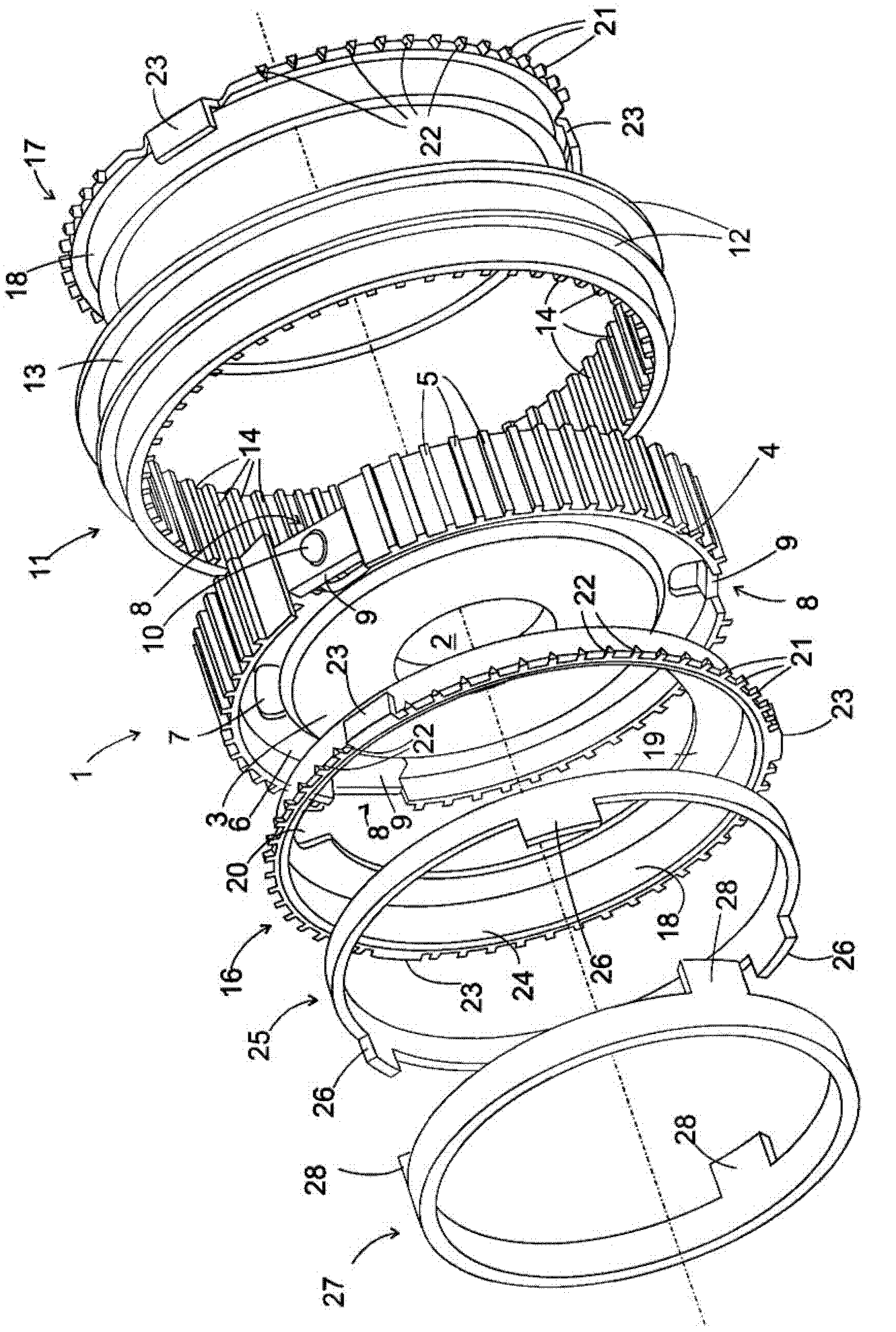
[0025] figure 1 is an exploded view of a double-acting synchronizer according to the present invention. The synchronizer comprises a hub 1 adapted to be non-rotatably splined to a shaft (not shown) extending through a central bore 2 of the hub 1 . The central part of the hub is in the form of a disc 3 and the tubular part 4 has engaging teeth 5 extending along the circumference of the disc 3 . Near the periphery of the disc 3 , an annular groove 6 is formed in the disc 3 and three shallow recesses 7 are formed in the groove 6 . exist figure 1 , only one of the three recesses 7 can be seen.

[0026] Three cutouts 8 are formed in the tubular portion 4 and extend well into the annular groove 6 of the disc 3 . Within the cutouts 8 are located booster blocks 9, each comprising a ball 10 biased radially outwards by a spring (not shown).

[0027] The tubular sleeve 11 has on its circumference two annular ribs 12 forming grooves 13 for engagement by a fork (not shown). The shift...


PUM

PropertyMeasurementUnit
Top angleaaaaaaaaaa
Top angleaaaaaaaaaa

Abstract

A double-acting synchronizer comprises a shaft (31), first and second gearwheels (29, 30) rotatably mounted on said shaft (31), a sleeve (11) which is axially displaceable along said shaft (31) between a position in which it locks the first gearwheel (30) to the shaft (31) and a position in which it locks the second gearwheel (29) to the shaft (31). A single conical friction surface (24) is formed between a first baulk ring (17) and the first gearwheel (30), and multiple nested conical friction surfaces are formed between a second baulk ring (16) and the second gearwheel (29).

Description

technical field [0001] The present invention relates to double-acting synchronizers and transmissions, in particular for motor vehicles in which the synchronizers are used. Background technique [0002] Double acting synchronizers generally have a hub that is splined to a shaft that also contains the two gears to which the synchronizer is connected. The sleeve is axially movable along the shaft between a neutral position and a displaced position in which the sleeve locks one of the two gears to the shaft. As long as the rotational speed of these gears is significantly different from the rotational speed of the shaft, the dog teeth of the bushing cannot engage the gears. A blocking ring is provided between the hub and each gear to prevent the mating teeth from grinding on the gear. If the sleeve is determined to be in its neutral position, it can displace the blocking ring, frictionally synchronizing the attached gear to the shaft. Only when synchronization is obtained, th...

Claims


Application Information

Patent Timeline
IPC IPC(8): F16D23/06
CPCF16D23/06F16D2023/0681F16D2023/0656F16D2023/0618
Inventor J.斯波尔德J.阿佩尔肖瑟H-J.扎克T.科克斯
Owner GM GLOBAL TECH OPERATIONS LLC
Why Eureka
Try Eureka