Method for defoaming pipeline from mouth of gas well to separator by using solid defoamer device

A solid defoamer and separator technology, applied in wellbore/well parts, foam dispersion/prevention, production of fluid, etc., can solve the problems of increased maintenance cost, incomplete defoaming, complex equipment structure, etc., to save production The effect of maintenance cost, reduction of operation labor intensity and simple equipment structure

Active Publication Date: 2012-04-25
成都孚吉科技有限责任公司
View PDF2 Cites 6 Cited by
  • Summary
  • Abstract
  • Description
  • Claims
  • Application Information

AI Technical Summary

Problems solved by technology

The equipment required for this process is complex in structure and vulnerable to damage, which not only affects the defoaming effect but also increases maintenance costs; at the same time, it needs to dilute the agent every day, which is labor-intensive. More importantly, because the injection state of the plunger pump is in a dot-line state, The contact surface between the foam and the defoamer is small, and the fluid flow rate in the pipeline is very fast, resulting in a lot of foam not being able to contact the defoamer, sometimes the defoaming is not complete, and accidents of foam tower overturning occur
This problem has always affected the effective development of foam drainage and gas recovery technology
[0003] Moreover, since natural gas wells have liquid discontinuity, sometimes the foam produced is relatively abundant, and sometimes there is no foam produced, and because the gas pipeline is a sealed system, its internal conditions cannot be observed from the surface. Affects the defoaming process. Traditional liquid defoamers are added continuously, sometimes for 24 hours.
Therefore, when the gas well does not produce liquid, the defoamer is also injected, resulting in waste of the defoamer; in addition, when the gas well produces a large amount of liquid and the foam is rich, because the injection of the defoamer is not increased in time If the amount of defoaming is not timely, it will also lead to the occurrence of foam tower overturning accidents

Method used


Image

  • Method for defoaming pipeline from mouth of gas well to separator by using solid defoamer device
  • Method for defoaming pipeline from mouth of gas well to separator by using solid defoamer device
  • Method for defoaming pipeline from mouth of gas well to separator by using solid defoamer device

Examples


Embodiment Construction

[0019] The present invention will be further described below in conjunction with accompanying drawing, but protection scope of the present invention is not limited to the following:

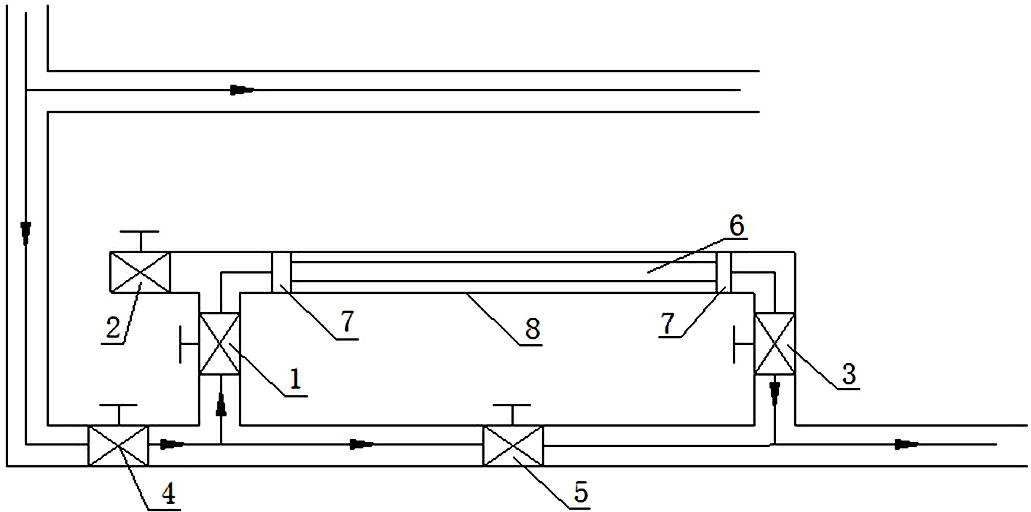
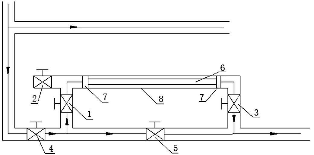
[0020] The solid defoamer device eliminates the foam in the gas well wellhead to the separator pipeline, such as figure 1 As shown, a solid defoamer device is installed in a bypass mode at a position about 30 meters away from the separator from the wellhead of the gas well to the gas transmission line of the separator. The solid defoamer device includes a main body 8, an inlet valve 1, and a packing valve 2 , Outlet valve 3, valve A4 is installed on the main line, valve B5 is installed on one end pipeline connected in parallel with the solid defoamer device, and the solid defoamer is placed in the main body 8 of the solid defoamer device through the filling valve 2.

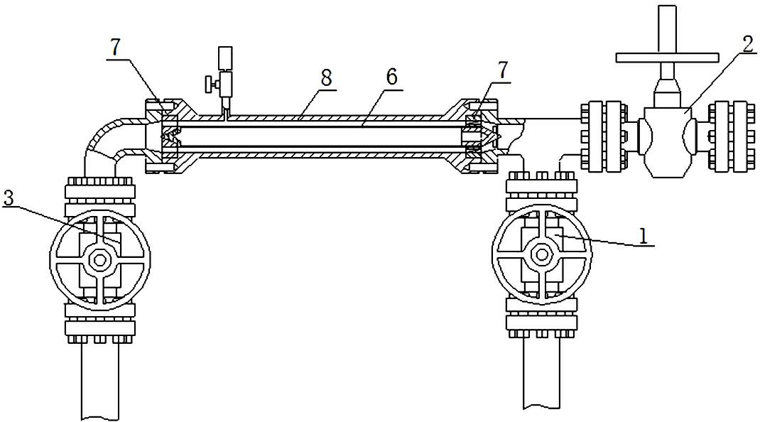
[0021] Such as figure 2 As shown, a fixed net 6 is installed in the main body 8 of the solid defoamer device, and the specially ...


PUM


Abstract

The invention discloses a method for defoaming a pipeline from the mouth of a gas well to a separator by using a solid defoamer device. The method comprises the following steps of: mounting the solid defoamer device on the gas transmission pipeline between the mouth of the natural gas well and the separator; specially making a defoamer be in a solid state and putting the solid defoamer into the solid defoamer device; enabling the solid defoamer to be in direct contact with transmission fluid; and dissolving the solid defoamer by the transmission fluid. The method has the beneficial effects that: the method is energy-saving and consumption-reducing and has no need of using a plunger pump and electric energy; the solid defoamer device has an automatic adjustment function, when liquid is produced, the solid defoamer is dissolved, when the liquid producing capacity is larger, more solid defoamer is dissolved, and thus, the waste of pharmaceutical products is avoided; the solid defoamer is placed in the solid defoamer device at a time and can be used for a number of days, and the daily putting is not needed, so that the cost for production and maintenance of the gas well is greatly saved, the technical difficulty and the labor intensity in operation are reduced, and the labor power is saved; and the fluid is in sufficient contact with the solid defoamer, the defoaming is complete, and the accident that foams cross a tower can be effectively prevented, so that the method is safe and reliable.

Description

technical field [0001] The invention relates to the technical field of foam elimination technology in the pipeline from the wellhead of the natural gas well to the separator, in particular to a method for eliminating foam in the pipeline from the wellhead of the gas well to the separator with a solid defoamer device. Background technique [0002] Gas wells need defoaming before the foam enters the separator after the foam drainage agent is injected, so as to achieve better gas-liquid separation. At present, the method of adding defoamer in the foam drainage gas recovery process is: inject liquid defoamer into the pipeline with a plunger pump to eliminate the foam in the pipeline. The equipment required for this process is complex in structure and vulnerable to damage, which not only affects the defoaming effect but also increases maintenance costs; at the same time, it needs to dilute the agent every day, which is labor-intensive. More importantly, because the injection stat...

Claims


Application Information

Patent Timeline
Patent Type & Authority Applications(China)
IPC IPC(8): B01D19/02E21B43/34
Inventor 戚杰李相云刘伟
Owner 成都孚吉科技有限责任公司
Why Eureka
Try Eureka