Method for positioning and clamping welding receiver lathing installation edges and device

A technology of welding casing and turning processing, which is applied in positioning devices, metal processing equipment, metal processing mechanical parts, etc., to solve the assembly error and the low efficiency of the clamping alignment process, meet the machining requirements, and shorten the production cycle.

Active Publication Date: 2012-04-25
SHENYANG LIMING AERO-ENGINE GROUP CORPORATION
View PDF3 Cites 53 Cited by
  • Summary
  • Abstract
  • Description
  • Claims
  • Application Information

AI Technical Summary

Problems solved by technology

[0003] In order to overcome the defects and insufficiencies of the existing clamping and positioning device for welding casing shell installation while welding, the present invention provides a method for clamping while welding casing processing and installation. The method is based on the same benchmark principle, The clamping structure design of the large and small mounting sides is integrated, and the partial reversible structure is used to realize the expansion and tightening of the large diameter end mounting side, and the overall fixture is used to realize the coaxial assembly of the large and small mounting sides under the condition of the same reference; the specific installation The clamping steps are as follows:

Method used


Image

  • Method for positioning and clamping welding receiver lathing installation edges and device
  • Method for positioning and clamping welding receiver lathing installation edges and device
  • Method for positioning and clamping welding receiver lathing installation edges and device

Examples


Embodiment Construction

[0014] The present invention will be further described below in conjunction with the accompanying drawings and embodiments.

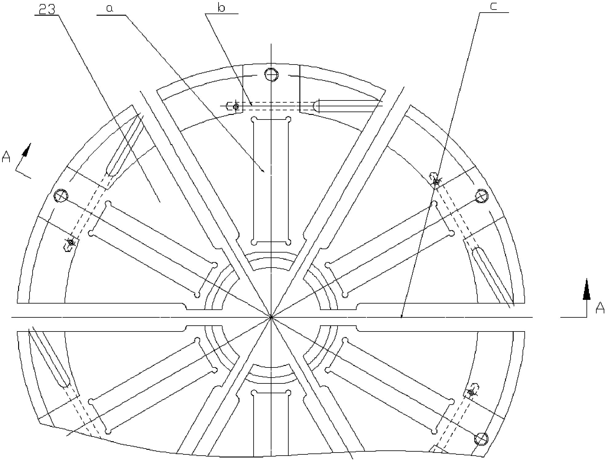
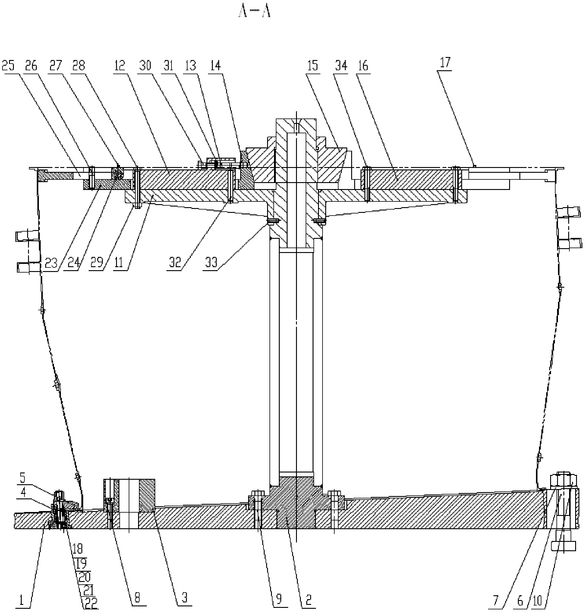
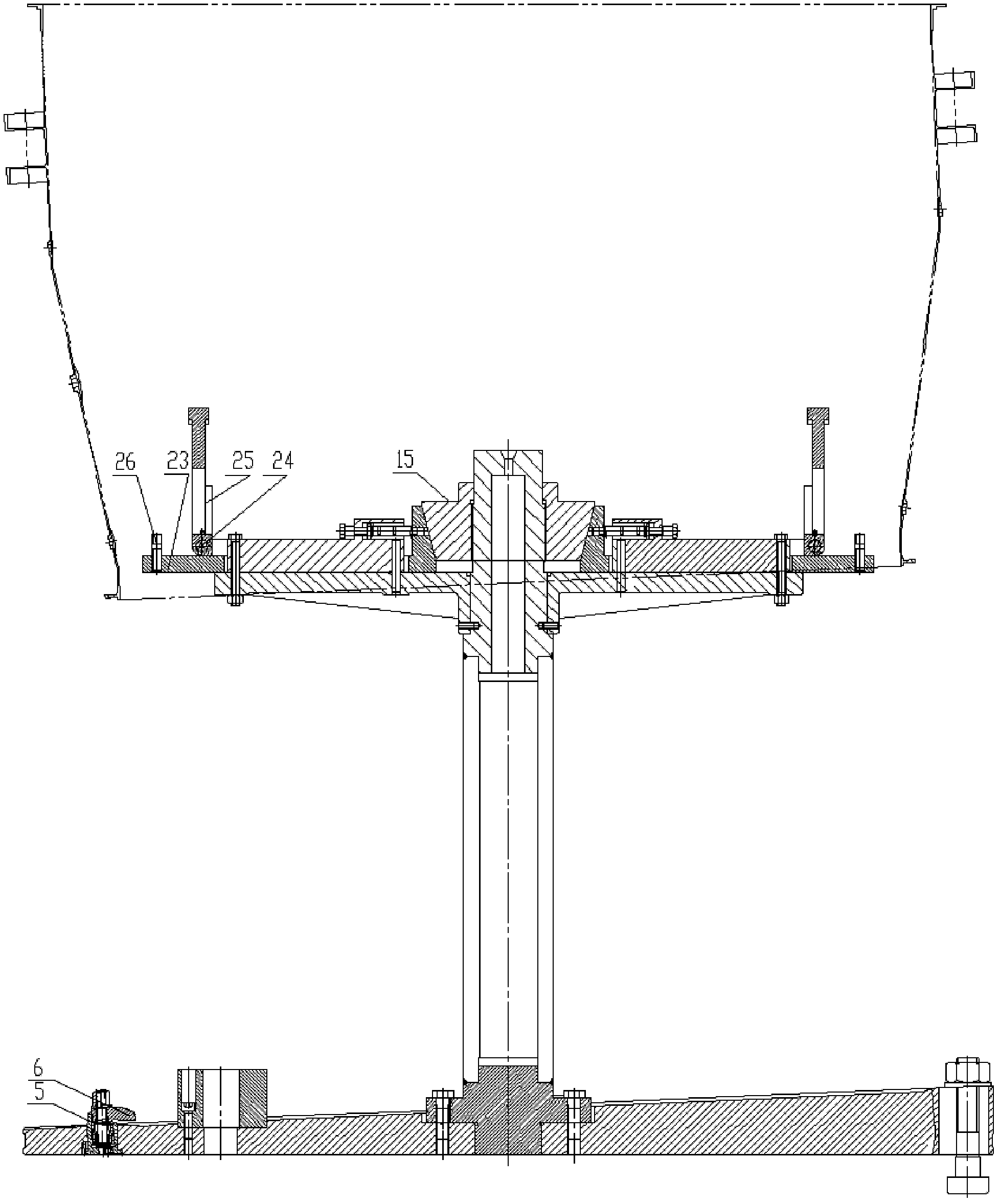
[0015] The device provided by the present invention for clamping while machining and installing welding casings is composed of a fixed clamping mechanism and an expansion and positioning mechanism. The fixed clamping mechanism includes a chassis 1, a mandrel 2, a counterweight 3 and a pressure hook 5 , the chassis 1 with a positioning notch is fixed on the fixture installation base by the compression bolt 6, the mandrel 2 is coaxial with the chassis 1 and the lower end is fixedly connected to the chassis 1 by the bolt I9, and the counterweight 3 is fixed by the stop screw 8 Fixed on the side of the small end of the chassis 1, the pressure hook 5 is installed on the end of the chassis 1 through the assembly formed by the stud 19, the nut II18 and the nut III21, and the stud 19 is provided with a spring I20 and a sleeve 4 for fixing and pressing Parts; th...


PUM


Abstract

The invention provides a method for positioning and clamping welding receiver lathing installation edges and a device. In the method, according to the principle of the same basis, a large and a small installation edge positioning and clamping structures are designed into a whole; expansion of the installation edge on a large-diameter end is realized by adopting a partially rotatable structure; assembly, expansion and co-axis of the large and small installation edges are realized by applying the condition that the same basis is used for a whole clamp; in the whole clamp, the clamp expansion part of a conventional structure is designed into an expansion block structure capable of rotating, locking and releasing; the expansion block structure and a positioning block are matched for realizing positioning and expansion of the installation edges of a part on the large and the small ends; machining requirements of the installation edges are satisfied; the problems of assembly errors and low efficiency of positioning, clamping and aligning processes due to use of a traditional splitting clamp in thin wall welding receiver lathing installation edges are solved; part assembly precision and processing efficiency are enhanced; and a production period is shortened.

Description

technical field [0001] The invention belongs to the technical field of mechanical processing, and in particular relates to a method and device for clamping while processing and installing welding casings. Background technique [0002] The welded receiver shell is mainly composed of the main body, the large mounting side and the small mounting side. The difference in inner diameter between the large mounting side and the small mounting side is relatively large. When clamping parts, the mounting edge of the small end cannot pass through the expansion block of the large end fixture. The ordinary expansion mechanism cannot achieve such a large difference in expansion, so it can only be designed as a split structure. The fixture chassis positioning device is installed on the lathe faceplate for Positioning and clamping small end mounting edge, while the large end mounting edge expansion mechanism is installed on the tailstock of the lathe. The tooling with this structure is cl...

Claims


Application Information

Patent Timeline
Patent Type & Authority Applications(China)
IPC IPC(8): B23Q3/06
Inventor 高献娟黄青松尹君方连军肖艳峰
Owner SHENYANG LIMING AERO-ENGINE GROUP CORPORATION
Why Eureka
Try Eureka