
Reinforcement protective structure of large spoil disposal area in mountainous area

A large-scale technology for dregs dumps, which is applied in the field of reinforcement and protection structures for large dregs dumps in mountainous areas, to achieve good environmental protection, simple construction technology, and good stability

Active Publication Date: 2012-04-25
CHINA RAILWAY ERYUAN ENG GRP CO LTD
View PDF6 Cites 7 Cited by
  • Summary
  • Abstract
  • Description
  • Claims
  • Application Information

AI Technical Summary

Problems solved by technology

[0003] The technical problem to be solved by the present invention is to provide a reinforcement and protection structure for large-scale waste dregs in mountainous areas, which can effectively solve the technical problems of stability of large-scale waste dregs in mountainous areas, reduce water and soil loss, and avoid man-made geological disasters caused by waste dregs

Method used


Image

  • Reinforcement protective structure of large spoil disposal area in mountainous area
  • Reinforcement protective structure of large spoil disposal area in mountainous area
  • Reinforcement protective structure of large spoil disposal area in mountainous area

Examples


Embodiment Construction

[0015] The present invention will be further described below in conjunction with the accompanying drawings and embodiments.

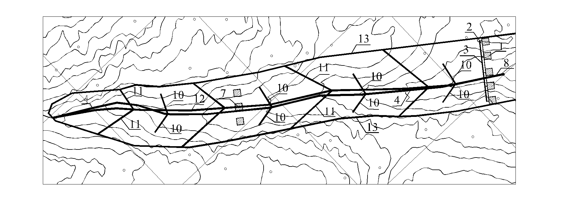
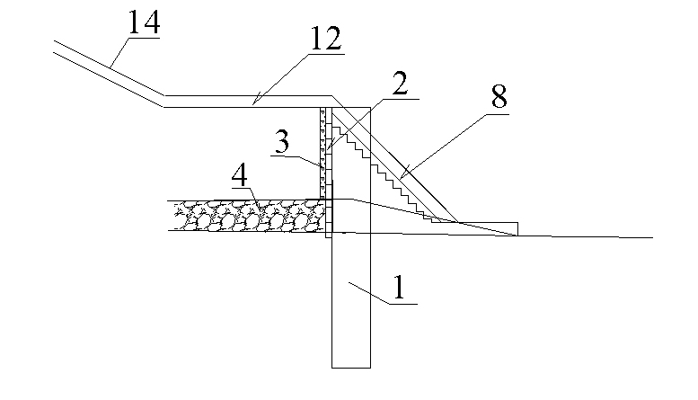
[0016] refer to figure 1 and figure 2 , the reinforcement and protection structure of the large-scale dregs field in mountainous area of ​​the present invention comprises: anti-slide pile 1, is arranged on the foot of slope of the outlet of the muck field, and is arranged at intervals along the transverse direction of the groove; On the side of the field; the gravel anti-filter layer 3 is filled behind the earth retaining plate 2; the main seepage blind ditch 4 is arranged longitudinally along the center of the ditch at the bottom of the dregs dump; the branch seepage ditch 10 is arranged along the center of the ditch at the bottom of the dregs dump Arranged in the form of branches on both sides of the hillside, connected with the main seepage blind ditch 4; the annular intercepting ditch 13 is arranged along the surrounding mountains above the top el...


PUM

PropertyMeasurementUnit
Depthaaaaaaaaaa
Widthaaaaaaaaaa
Depthaaaaaaaaaa

Abstract

The invention discloses a reinforcement protective structure of a large spoil disposal area in a mountainous area, which is capable of effectively solving the technical problem of instability of the large spoil disposal area in the mountainous area, reducing water loss and soil erosion and avoiding the anthropogenic geologic hazard problems caused by the abandoned spoil. The reinforcement protective structure comprises anti-slide piles, a retaining plank, a macadam reversed filter, a main water seepage blind ditch, branch water seepage blind ditches, an annular catchwater, a longitudinal drainage trench, catchwaters and a drainage chute, wherein the anti-slide piles are arranged on an exit slope toe of the spoil disposal area and distributed at intervals along the cross direction of a groove; the retaining plank is arranged on the side of the anti-slide piles near to the spoil disposal area; the macadam reversed filter is filled behind the retaining plank; the main water seepage blind ditch is longitudinally arranged along the center of the groove on the bottom of the spoil disposal area; along the centre of the groove on the bottom of the spoil disposal area, the branch water seepage blind ditches are distributed in the shape of branches toward slopes on two sides and communicated with the main water seepage blind ditch; the annular catchwater is arranged along the surrounding mountain having more than 1m elevation from the top of the spoil disposal area, and stretched and connected to a natural groove on the exit of the spoil disposal area; the longitudinal drainage trench is arranged along the top center of the spoil disposal field and communicated with the natural groove; the catchwaters are arranged in the shape of branches from the longitudinal drainage trench of the spoil disposal area to the top two sides of the spoil disposal area and communicated with the longitudinal drainage trench; the drainage chute is arranged outside the retaining plank.

Description

technical field [0001] The invention relates to the reinforcement and protection of dreg sites for railways, highways, water conservancy and the like, and particularly relates to a reinforcement and protection structure for large dreg sites in mountainous areas. Background technique [0002] With the construction of a large number of road projects, water conservancy projects and local infrastructure in my country, a large number of excavated dregs have appeared. According to the requirements of environmental protection, it is necessary to centrally discard the dregs. Due to terrain constraints in mountainous areas of our country, there is often a huge amount of dregs excavated in engineering construction, and dregs can only be concentrated and discarded in mountainous trenches. It not only meets the requirements of environmental protection, but also has a reinforcement and protection structure for the dregs field with simple construction technology and saving engineering inv...

Claims


Application Information

Patent Timeline
IPC IPC(8): E02D17/20E03F1/00
Inventor 姚裕春朱颖李安洪叶世斌庞应刚李楚根曾永红李井元
Owner CHINA RAILWAY ERYUAN ENG GRP CO LTD
Learn More