Dynamic pressure lubrication drilling tool and drilling tool assembly with same

A drilling tool assembly and drilling tool technology, applied in drill pipe, drill pipe, drilling equipment, etc., can solve the problem of automatic separation between the outer surface of the drilling tool and the well wall or casing wall, so as to improve drilling efficiency and prevent well deviation. , the effect of reducing friction loss and surface wear

Inactive Publication Date: 2012-04-25
CHINA UNIV OF PETROLEUM (BEIJING)
View PDF7 Cites 10 Cited by
  • Summary
  • Abstract
  • Description
  • Claims
  • Application Information

AI Technical Summary

Problems solved by technology

[0004] At present, most of the existing anti-deflection and straightening technologies are represented by the above-mentioned known technologies. They can only prevent or correct deviation through direct contact between the drilling tool and the well wall or casing wall when the well deviation has occurred. Realize that the outer surface of the drilling tool is automatically separated from the well wall or casing wall during drilling, so that the drilling tool automatically tends to the center of the borehole to prevent the occurrence of well deviation. Therefore, in the known technology, rapid drilling and anti-deflection drilling Straight contradictions still exist

Method used


Image

  • Dynamic pressure lubrication drilling tool and drilling tool assembly with same
  • Dynamic pressure lubrication drilling tool and drilling tool assembly with same
  • Dynamic pressure lubrication drilling tool and drilling tool assembly with same

Examples


Embodiment Construction

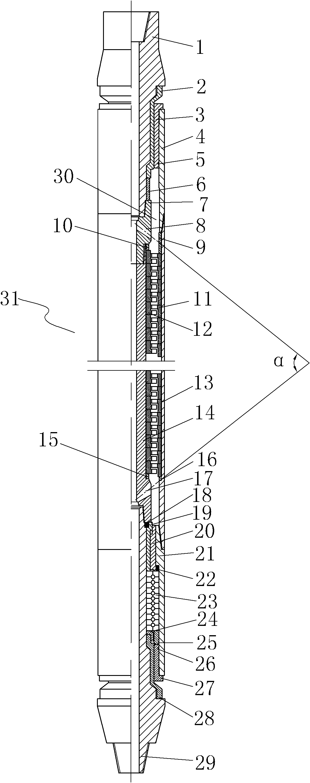
[0040] A dynamic pressure lubricating drilling tool proposed by the present invention includes: a hollow central shaft, a casing sleeved on the outside of the central shaft, and an inner wall of the casing and the outer peripheral surface of the central shaft are formed with a annulus; at least one or more rotors are arranged on the inner wall of the casing, each of the rotors has a plurality of inwardly protruding rotor blades, the rotor blades are located in the annulus; the central axis The side wall of the rotor is provided with more than one shunt hole, and the drilling fluid entering the central shaft can impact the rotor blade after passing through the shunt hole, so that the casing can rotate relative to the central axis.

[0041]Further, the central shaft is composed of an upper joint, a water cap joint, a central pipe, and a lower joint that are screwed and connected in sequence, and a plurality of the shunt holes are evenly distributed on the side wall of the water c...


PUM


Abstract

The invention relates to a dynamic pressure lubrication drilling tool and a drilling tool assembly. The dynamic pressure lubrication drilling tool comprises a central shaft, wherein a shell can be sleeved on the outer part of the central shaft in a rotating manner relative to the central shaft, and an annular space is formed between the inner wall of the shell and the peripheral surface of the central shaft; more than one rotor is arranged on the inner wall of the shell, each rotor is provided with a plurality of inwards protruding rotor blades, and the rotor blades are positioned in the annular space; and the side wall of the central shaft is provided with more than one shunting hole. The drilling tool assembly is provided with a drill column, wherein the drill column comprises a plurality of sequentially connected conventional drilling tools and at least one dynamic pressure lubrication drilling tool; and the dynamic pressure lubrication drilling tool is arranged between two adjacent conventional drilling tools. when a well is drilled, the drilling tool assembly brings drilling fluid to the space between the drilling tool and a well wall or a sleeve wall under the fluid pumping action when the dynamic pressure lubrication drilling tool rotates, and the outer surface of the drilling tool is separated from the well wall or the sleeve wall, so that dry friction or boundary friction between the outer surface of the drilling tool and the well wall or the sleeve wall is changed into fluid friction.

Description

technical field [0001] The invention relates to a drilling tool, in particular to a drilling tool that can use the pump fluid action when the drilling tool itself rotates to bring the drilling fluid into the friction surface between the outer surface of the drilling tool and the well wall or casing wall, so as to bring the outer surface of the drilling tool to the friction surface of the casing wall. The well wall or casing wall is separated, and the dry friction or boundary friction between the outer surface of the drilling tool and the well wall or casing wall is changed to liquid friction. A drill tool assembly to prevent well deviation. Background technique [0002] In the process of drilling, the problem of deviation prevention of vertical wells has always been one of the difficult problems in the field of oil and gas drilling, especially when drilling in inclined formations in high and steep structural areas, the problem of well deviation is very serious. For example,...

Claims


Application Information

Patent Timeline
Patent Type & Authority Applications(China)
IPC IPC(8): E21B17/18E21B17/042E21B7/10
Inventor 刘忠吴德银李珩
Owner CHINA UNIV OF PETROLEUM (BEIJING)
Why Eureka
Try Eureka