Full parameter detection apparatus of polished surface quality of optical element and detection method thereof

A technique for polishing surfaces, optical components, used in the use of optical devices, measuring devices, polarization-influenced properties, etc.

Active Publication Date: 2012-04-25
XIAN TECH UNIV
View PDF5 Cites 15 Cited by
  • Summary
  • Abstract
  • Description
  • Claims
  • Application Information

AI Technical Summary

Problems solved by technology

However, the detection effect of confocal laser scanning microscope is not ideal, because the subsurface damage is hidden under the surface, complex and hidden, and its detection is very difficult
Therefore, there are two problems in the current detection of polished surface quality parameters: 1) only the surface roughness is detected; 2) even if the sub-surface damage is detected, since the roughness measurement is not carried out on the same equipment, the surface roughness of the detection cannot be achieved It is the same area on the component as the subsurface damage, so it cannot truly reflect the surface quality of the evaluated area

Method used


Image

  • Full parameter detection apparatus of polished surface quality of optical element and detection method thereof
  • Full parameter detection apparatus of polished surface quality of optical element and detection method thereof

Examples


Embodiment Construction

[0022] The present invention will be further described below in combination with specific embodiments and accompanying drawings.

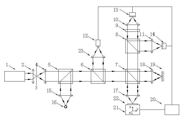
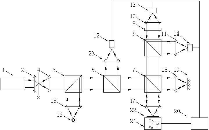
[0023] A full-parameter detection device for polishing surface quality of optical components, including a light source excitation system composed of a laser excitation system with a vertical optical path and a broadband light source 16 excitation system, a white light interference system, a laser confocal detection system, a computer, and CCDs connected to the computer respectively Camera 12, pinhole photodetector and signal processing unit 13, aperture photodetector and signal processing unit 14, and three-dimensional scanning and control unit 21; the white light interference system is arranged between the broadband light source 16 excitation system and the CCD camera 12 The laser confocal detection system is set between the laser excitation system, the pinhole photodetector and the signal processing unit 13, the aperture photodetector and the sign...


PUM


Abstract

The invention relates to a full parameter detection apparatus of a polished surface quality of an optical element and a detection method thereof. According to an existing polished surface quality parameter detection method and an apparatus thereof, a surface quality of an evaluated region can not be reflected really. According a technical scheme employed in the invention, a full parameter detection apparatus of a polished surface quality of an optical element is provided; the apparatus comprises a light source excitation system, a white light interference system, a laser confocal detection system, a computer, a CCD camera, a pinhole photoelectric detector and signal processing unit, a diaphragm photoelectric detector and signal processing unit and a three dimensional scanning and control unit; the light source excitation system is formed by a laser excitation system and a broadband light source excitation system, wherein optical paths of the laser excitation system and the broadband light source excitation system are vertical; and the CCD camera, the pinhole photoelectric detector and signal processing unit, the diaphragm photoelectric detector and signal processing unit and the three dimensional scanning and control unit are respectively connected with the computer. Moreover, the white light interference system is arranged between the broadband light source excitation system and the CCD camera; and the laser confocal detection system is arranged between the laser excitation system and the pinhole photoelectric detector and signal processing unit and the diaphragm photoelectric detector and signal processing unit. According to the invention, a surface quality of an evaluated region can be reflected effectively and really.

Description

technical field [0001] The invention belongs to the technical field of optical element polishing surface quality detection, and in particular relates to an optical element polishing surface quality full-parameter detection device and detection method. Background technique [0002] The detection of high-precision optical components includes three parameters: surface shape, surface roughness and subsurface damage. Among them, surface roughness and subsurface damage are two parameters that fully describe the surface quality. For the full-parameter detection of the polished surface quality of optical components, the problem of surface roughness detection has basically been solved at present. The detection methods for surface roughness mainly include optical probe method, interference microscope method, scanning electron microscope method, profilometer and scattered light. The more mature one is the white light interference profiler; the white light interference profiler include...

Claims


Application Information

Patent Timeline
Patent Type & Authority Applications(China)
IPC IPC(8): G01B11/30G01N21/21
Inventor 田爱玲王红军刘丙才王春慧王辉朱学亮
Owner XIAN TECH UNIV
Why Eureka
Try Eureka