Component shaping and inserting mechanism for component inserting machine

A plug-in machine and plug-in technology, applied in electrical components, electrical components and other directions, can solve the problems of affecting the normal production of plug-in machines, high manufacturing cost, popularization and application, and tedious equipment maintenance work, and achieve simple structure, low manufacturing cost and practicality. strong effect

Inactive Publication Date: 2012-04-25
DONGGUAN SCIENCGO MACHINERY MFG
View PDF6 Cites 14 Cited by
  • Summary
  • Abstract
  • Description
  • Claims
  • Application Information

AI Technical Summary

Problems solved by technology

However, the existing plug-in machine head plug-in mechanism is difficult to be popularized and applied due to its complex structure and high manufacturing cost. Due to the complex structure, the equipment maintenance work is also relatively cumbersome, and the equipment is prone to jamming during processing, which seriously affects the plug-in machine. Normal production with obvious defects

Method used


Image

  • Component shaping and inserting mechanism for component inserting machine
  • Component shaping and inserting mechanism for component inserting machine
  • Component shaping and inserting mechanism for component inserting machine

Examples


Embodiment Construction

[0025] In order to facilitate the understanding of those skilled in the art, the present invention will be further described below in conjunction with the embodiments and accompanying drawings, and the contents mentioned in the embodiments are not intended to limit the present invention.

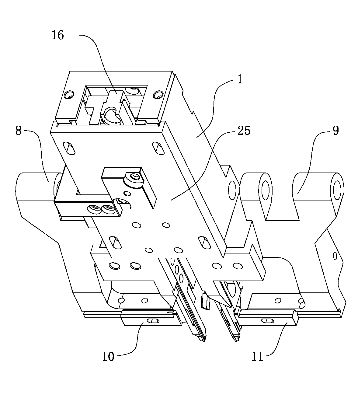
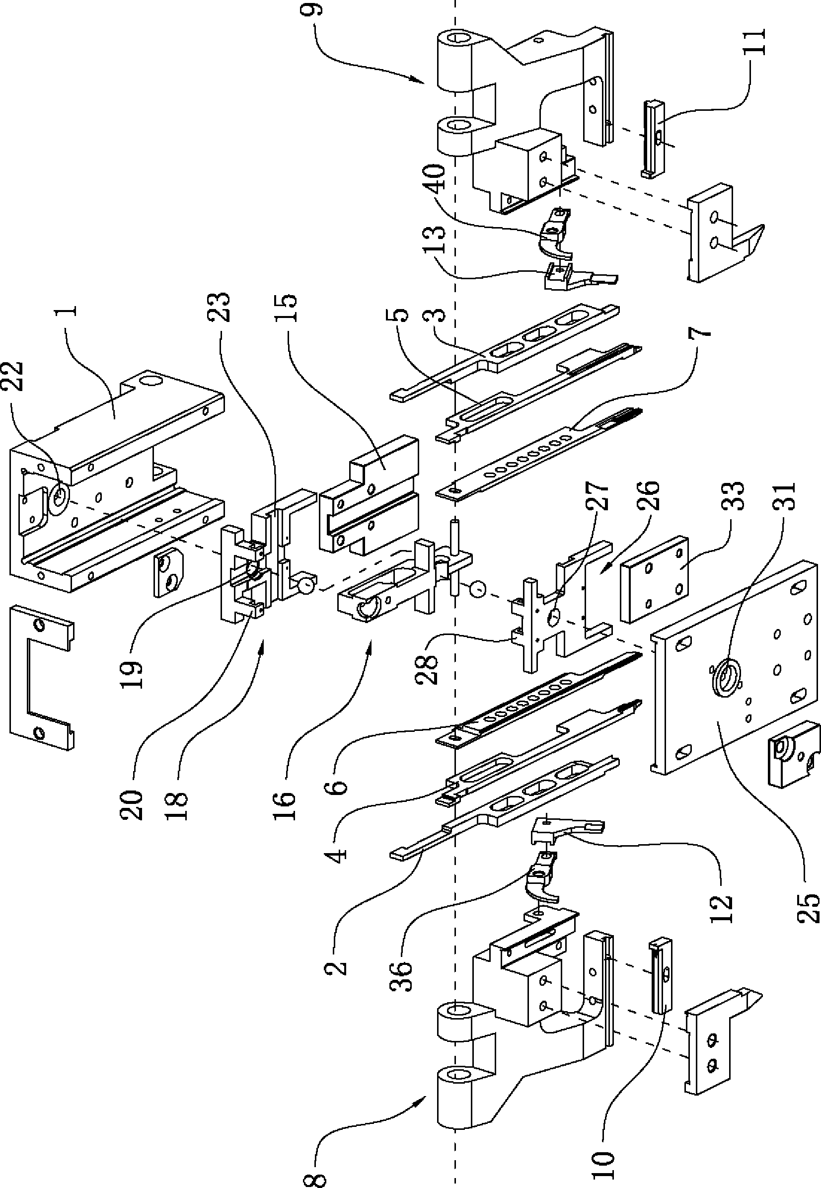
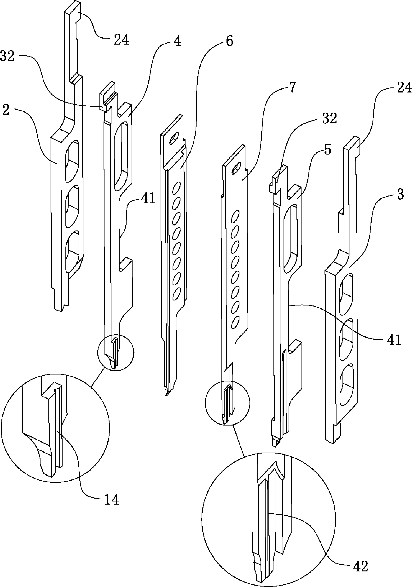
[0026] Such as Figure 1 to Figure 9 Shown, a plug-in machine plastic plug-in mechanism, including a knife box 1, a knife set set in the knife box 1 and a linkage mechanism that drives the knife set to move up and down, the knife set includes a left cutter 2, a right cutter 3, a left cutter Forming knife 4, right forming knife 5, left pushing knife 6, right pushing knife 7, the left cutting knife 2, left forming knife 4, left pushing knife 6, right pushing knife 7, right forming knife 5, right cutting knife 3 From left to right, it is installed in the knife box 1 sequentially; the bottom of the knife box 1 is provided with a left knife rest 8 and a right knife rest 9, and the bottom of the l...


PUM


Abstract

The invention relates to the technical field of electronic component insertion, in particular to a component shaping and inserting mechanism for a component inserting machine. The component shaping and inserting mechanism comprises a tool box, a tool group and a link gear, wherein the tool group comprises a left-cut tool, a right-cut tool, a left molding tool, a right molding tool, a left push-type broach and a right push-type broach, wherein the left-cut tool, the left molding tool, the left push-type broach, the right push-type broach, the right molding tool and the right-cut tool are sequentially and movably arranged in the tool box from left to right; a left tool rest and a right tool rest are arranged at the lower part of the tool box, a left undercut tool and a right undercut tool are respectively assembled at the lower part of the left tool rest and the right tool rest, and the left tool rest and the right tool rest are respectively and movably provided with a left auxiliary molding tool and a right auxiliary molding tool; and pin guiding slots are respectively formed at the inner sides of the lower end parts of the lower end parts of the left molding tool and the right molding tool. The component shaping and inserting mechanism for the component inserting machine, disclosed by the invention, has the advantages of simple structure, low manufacturing cost, and no equipment locking phenomenon in a machining process, thus, the stability during component shaping and inserting machining is greatly increased, the inserting efficiency of the component inserting machine is increased, and the practicability is strong.

Description

technical field [0001] The invention relates to the technical field of electronic component insertion, in particular to a shaping insertion mechanism for an insertion machine. Background technique [0002] With the rapid development of electronic technology, the use of electronic products is becoming more and more extensive. PCB circuit boards are an important carrier of electronic products, and plug-in machines are processing equipment that insert various electronic components into designated positions on PCB circuit boards. During the processing of the plug-in machine, the electronic components are generally transported to the top of the PCB board by the clamping device for positioning, and then the clamping device moves down to accurately insert the electronic components into the preset pins of the PCB circuit board. In the socket, then the clamping device is reset to facilitate the clamping of new electronic components for the next plug-in processing. The inserted electr...

Claims


Application Information

Patent Timeline
Patent Type & Authority Applications(China)
IPC IPC(8): H05K13/04B21F11/00B21F1/00
Inventor 皮俊君王媛秀曾翔清陈卓标
Owner DONGGUAN SCIENCGO MACHINERY MFG
Why Eureka
Try Eureka