Convex Crested Insert With Deflected Wedge Surfaces

Active Publication Date: 2010-12-02
KINGDREAM PLC CO
View PDF2 Cites 7 Cited by
  • Summary
  • Abstract
  • Description
  • Claims
  • Application Information

AI Technical Summary

Benefits of technology

[0015]Technical benefits of the present invention include: 1. When the insert of this invention is used as heel row cutter on bit, the middle uppermost portion of the top surface of the insert contact formation rock first, and then ends of the insert crest contact the formation rock gradually. Therefore, contact area between the insert and formation rock is very small at the very beginning, so the partial contact stress applied on the rock is higher and this could be beneficial for rock breaking and thus increasing drilling efficiency of the insert and reducing overall drilling costs. 2. Because the top surface of the insert is higher in the middle and lower at both sides, the high stress normally encountered with conventional insert at both sides of the insert due to edge effect is effectively reduced, and therefore, rate of breakage at sides of the to

Problems solved by technology

Heel row cutters normally used on roller cone bits of prior art include inserts with deflected wedge surfaces and conical spherical inserts, which can not meet the two requirements mentioned above simultaneously.
But this insert has a blunter top surface because there is a plain on the top surface of the insert, and so it is not beneficial to breaking bottom hole rocks by impact actions.
When inserts with deflected wedge surfaces are used as heel row cutters on

Method used


Image

  • Convex Crested Insert With Deflected Wedge Surfaces
  • Convex Crested Insert With Deflected Wedge Surfaces
  • Convex Crested Insert With Deflected Wedge Surfaces

Examples


Embodiment Construction

[0025]Preferred embodiments of the invention and its advantages are best understood by reference to FIGS. 1-9 wherein like number refer to the same and like parts.

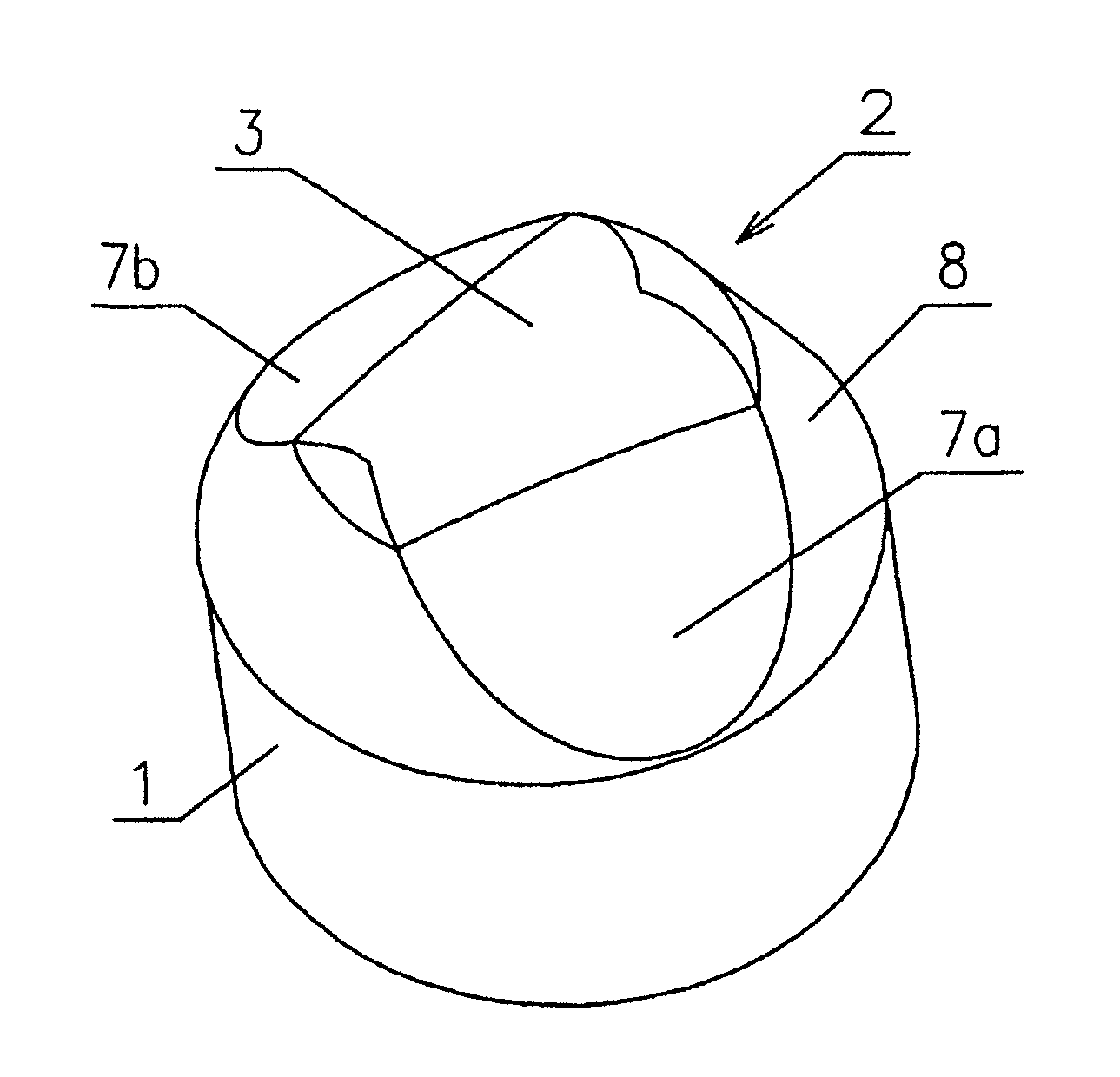
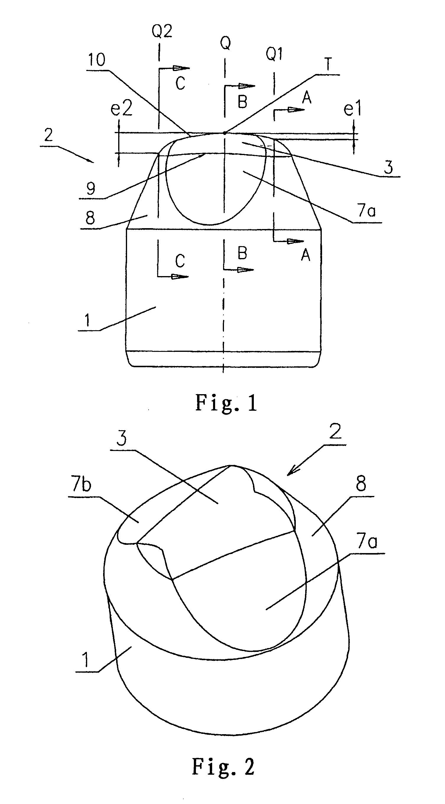
[0026]A convex crested insert with deflected wedge surfaces is disclosed which comprises a cylindrical portion 1 and a crest portion 2. The crest portion is further composed of a conical crest base 8, a top surface 3 and two opposing wedge surfaces 7a, 7b. An included angle between a generatrix of the crest base 8 and an axis of the cylindrical portion of the insert is 20°, and upper edges of the two wedge surfaces are merged with the top surface 3 of the insert.

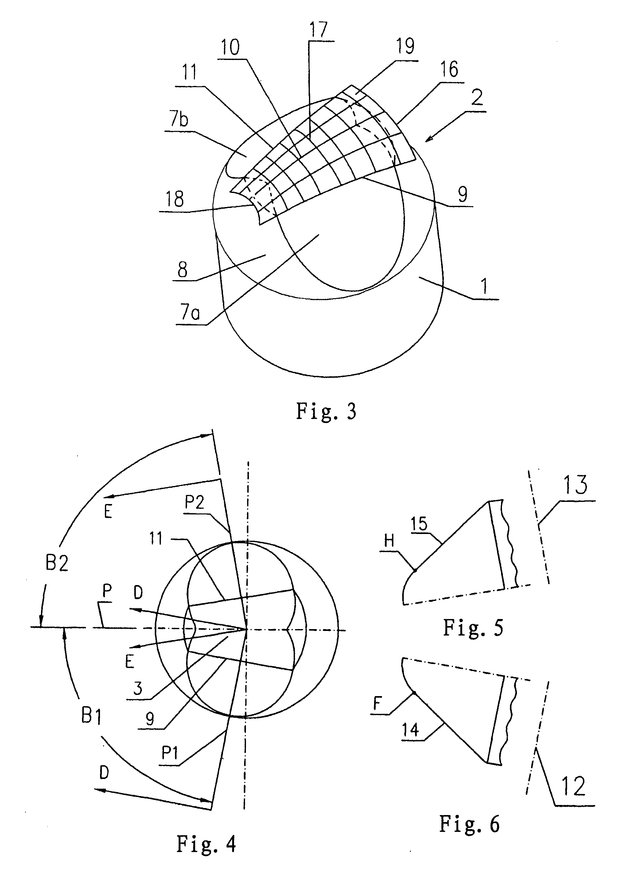
[0027]FIG. 4 shows three imaginary planes P, P1, P2 passing through the axis of the cylindrical portion of the insert, with two included angles B1, B2 formed between the plane P as a center plane of the insert crest and two lateral planes P1, P2. The two included angles B1, B2 might be ranged from 45° to 89°, and preferably from 70° to 85°.

[0028]The two wedge surfa...


PUM


Abstract

This invention relates to carbide inserts used on roller cone bits for oil and gas drilling applications as well as for other geological drilling applications, and more specifically, relates to the convex crested insert with deflected wedge surfaces. The insert comprises a cylindrical portion and a crest portion. Said crest portion is composed of a conical crest base, a top surface and two opposing wedge surfaces. Upper ends of the two wedge surfaces are merged smoothly with top surface of the insert. The specific feature of the structure is that top surface of the crest portion is convexed outwardly and forms a smooth curve surface which is higher in the middle and lowers down gradually to each end. Said two wedge surfaces are slant wedge surfaces, so that a width of the top surface and therefore a width of the insert crest are tapered from one end to the other. Advantages of this invention include: 1. Help for rock breaking and therefore, it can increase drilling efficiency of the cutters and lower the overall drilling cost; 2. higher anti-breakage capability and longer working life; and 3. when inserts of this invention are used as heel row cutting elements on bit, contact area between wider end of the top surface of the insert and borehole wall is larger and therefore the gouging action applied on the borehole wall is higher and can also achieve better gage protection of the bit.

Description

CROSS REFERENCE TO RELATED APPLICATIONS[0001]Pursuant to 35 USC §119, this application claims the benefit of Chinese Patent Application No. 200910062267.2 filed May 27, 2009. The above application is incorporated by reference in its entirety.TECHNICAL FIELD[0002]This invention relates to a carbide insert used on roller cone bits for oil and gas drilling applications as well as for other geological drilling applications, and more specifically, relates to a convex crested insert with deflected wedge surfaces.BACKGROUND OF THE INVENTION[0003]Roller cone bits are widely used in oil and gas, mining and engineering drilling applications. During drilling, heel row cutters on cones of the bit undertake multiple jobs including break bottom hole rocks by impact actions, gouge borehole wall and help to maintain bit diameter in order to prevent bit diameter shrinkage. Breaking bottom hole rocks by impact actions requires sharper top surface of the insert; gouging borehole wall and maintaining b...

Claims


Application Information

Patent Timeline
IPC IPC(8): E21B10/52E21B10/46E21B10/58E21B10/16
CPCE21B10/16E21B10/58E21B10/52
Inventor FAN, XIAOBINGWU, PENGCHEN, DONGFANGGUO, CHENGFU
Owner KINGDREAM PLC CO
Why Eureka
Try Eureka