
X-ray location-based focusing therapy unit and system

A technology of focus therapy and light positioning, which is applied in the field of focus therapy devices and systems, can solve problems such as human body damage, attenuation, and large incident energy, and achieve the effect of reducing attenuation and preventing attenuation

Inactive Publication Date: 2012-05-02
深圳市慧康医疗器械有限公司
View PDF4 Cites 6 Cited by
  • Summary
  • Abstract
  • Description
  • Claims
  • Application Information

AI Technical Summary

Problems solved by technology

[0002] Focusing and positioning devices for lesions are medical devices, and they are used very frequently in reality. They are used to locate lesions in the human body for further treatment. The current focusing and locating devices for lesions are mainly used in the process of use. Each component is adjusted. The existing technology uses ultrasonic waves for positioning. After positioning, the energy of the wave source is used to achieve focused treatment on the lesion. This existing positioning device requires a large incident energy of ultrasonic waves per unit area, and its positioning accuracy is low. It will also affect the focusing treatment effect on the lesion, and even cause certain damage to the human body. In addition, because the existing focus positioning treatment devices generally use water and other media to transmit the energy of the wave source, so as to achieve the purpose of focus treatment, but After x-ray energy passes through water and other media, it will cause serious attenuation. Therefore, the existing technology cannot realize x-ray-based positioning and focusing therapy, which largely limits the application of x-ray positioning-based focusing therapy

Method used


Image

  • X-ray location-based focusing therapy unit and system
  • X-ray location-based focusing therapy unit and system
  • X-ray location-based focusing therapy unit and system

Examples


Embodiment 1

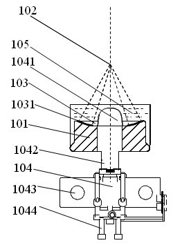
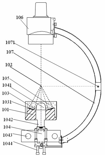
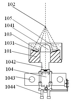
[0049] Such as figure 1 As shown, this example provides a focus therapy device based on X-ray positioning, including:

[0050] The first wave source assembly 101, the upper surface of which is a concave spherical member, the center of which is the focal point 102;

[0051] The second wave source assembly 103 includes at least two wave source components 1031 installed on the concave spherical component, and the wave source component 1031 has the same spherical center as the concave spherical component;

[0052] The positioning assembly 104 includes an inflatable balloon 1041, an x-ray channel 1042, an x-ray emitting member 1043, and an inflatable member 1044. The component 1043 is used to control the emission of x-rays, and the inflatable component 1044 is used to inflate the inflatable air bag 1041;

[0053] The medium container 105 is used to fill the medium and seal the first wave source assembly 101 .

[0054] Wherein, the upper surface of the first wave source component...

Embodiment 2

[0061] Different from Embodiment 1, the second wave source assembly 103 in this example includes at least two wave source components 1031 that work independently.

[0062] Wherein, the wave source components 1031 work independently, which means that the wave source components 1031 can select a single wave source component 1031 to work and a plurality of wave source components 1031 to work at the same time, and each wave source component 1031 can work independently. The second wave source assembly 103 includes at least two independently working wave source components 1031 , therefore, in this example, one or more of the wave source components 1031 can be selectively activated according to actual needs.

[0063] In the prior art, since the wave source may be hindered by bones and other objects that can easily absorb the energy of the wave source in a certain direction of incidence, if there is a bone blockage, there will be a dead angle that cannot be focused during the focused tre...

Embodiment 3

[0069] The difference from Embodiment 2 is that the wave source component 1031 in this embodiment adopts a magnetic disk, and the magnetic disk has the focal point 102 as the center of the sphere.

[0070] Wherein, the magnetic disk is a magnetic disk with a spherical structure, and each disk is centered at the focus point 102, including shock wave disks and ultrasonic disks. Each disk is centered at the focus point 102, and the spherical structure of the disk can be If a concave spherical surface structure is adopted, then in the process of focusing treatment, the wave source emitted by each working disk coincides with the focus point 102 to achieve focus treatment. In this example, the principle of inflating the inflatable airbag 1041 is used to discharge the medium, and then Realizing the location of the lesion based on x-rays can effectively reduce the attenuation of x-ray energy.

[0071] This example further adopts the above-mentioned technical features, and its advantag...


PUM


Abstract

The invention relates to an X-ray location-based focusing therapy unit and an X-ray location-based focusing therapy system. The X-ray location-based focusing therapy unit comprises a first wave source component (101), a second wave source component (103), a locating component (104) and a medium container (105); the upper surface of the first wave source component (101) is a concave spherical member of which the sphere centre is a focus (102); the second wave source component (103) comprises at least two wave source members (1031) mounted on the concave spherical member, and the wave source members (1031) and the concave spherical member share the sphere centre; the locating component (104) comprises an inflatable air bag (1041), an X ray passage (1042), an X ray-emitting member (1043) and an inflating member (1044), the inflatable air bag (1041) is connected with the X ray passage (1042), the axes of both the inflatable air bag (1041) and the X ray passage (1042) pass through the focus (102), the X ray-emitting member (1043) is used for controlling and emitting an X ray, and the inflating member (1044) is used for inflating the inflatable air bag (1041); and medium is filled in the medium container (105), and the medium container (105) is used for sealing the first wave source component (101). The unit and the system have the advantages that: the attenuation of X ray energy is little, the location is accurate, and thereby effective focusing therapy can be realized on the basis of X-ray focus location.

Description

technical field [0001] The invention relates to a focus therapy device, in particular to a focus therapy device and a system thereof based on X-ray positioning. Background technique [0002] Focusing and positioning devices for lesions are medical devices, and they are used very frequently in reality. They are used to locate lesions in the human body for further treatment. The current focusing and locating devices for lesions are mainly used in the process of use. Each component is adjusted. The existing technology uses ultrasonic waves for positioning. After positioning, the energy of the wave source is used to achieve focused treatment on the lesion. This existing positioning device requires a large incident energy of ultrasonic waves per unit area, and its positioning accuracy is low. It will also affect the focusing treatment effect on the lesion, and even cause certain damage to the human body. In addition, because the existing focus positioning treatment devices genera...

Claims


Application Information

Patent Timeline
Patent Type & Authority Applications(China)
IPC IPC(8): A61N7/00A61B17/225A61B6/00
Inventor 陈明
Owner 深圳市慧康医疗器械有限公司
Learn More