New steel tube positioning method used in steel tube conveying of tack welder and realization device

A technology of steel pipe transportation and positioning method, which is applied in the direction of auxiliary equipment, welding equipment, auxiliary welding equipment, etc., which can solve the problems of high action point, increase of propeller tipping moment, large propeller height and size, etc., and achieve small force , Small structure size and small tipping moment

Inactive Publication Date: 2012-05-02
TIANSHUI METALFORMING MACHINE TOOL GROUP
View PDF9 Cites 1 Cited by
  • Summary
  • Abstract
  • Description
  • Claims
  • Application Information

AI Technical Summary

Problems solved by technology

The following problems exist in the application of the conventional positioning method V-shaped roller table: 1. The height of the propeller is large, 2. The minimum diameter of the steel pipe is limited; 3. The action point is high when the force is large, and the action point is low when the force is small, resulting in a large tube The tipping moment of the propeller increases when the diameter steel pipes are jointed

Method used


Image

  • New steel tube positioning method used in steel tube conveying of tack welder and realization device
  • New steel tube positioning method used in steel tube conveying of tack welder and realization device
  • New steel tube positioning method used in steel tube conveying of tack welder and realization device

Examples


Embodiment Construction

[0019] The present invention and its beneficial effects will be further described in detail below in conjunction with the accompanying drawings.

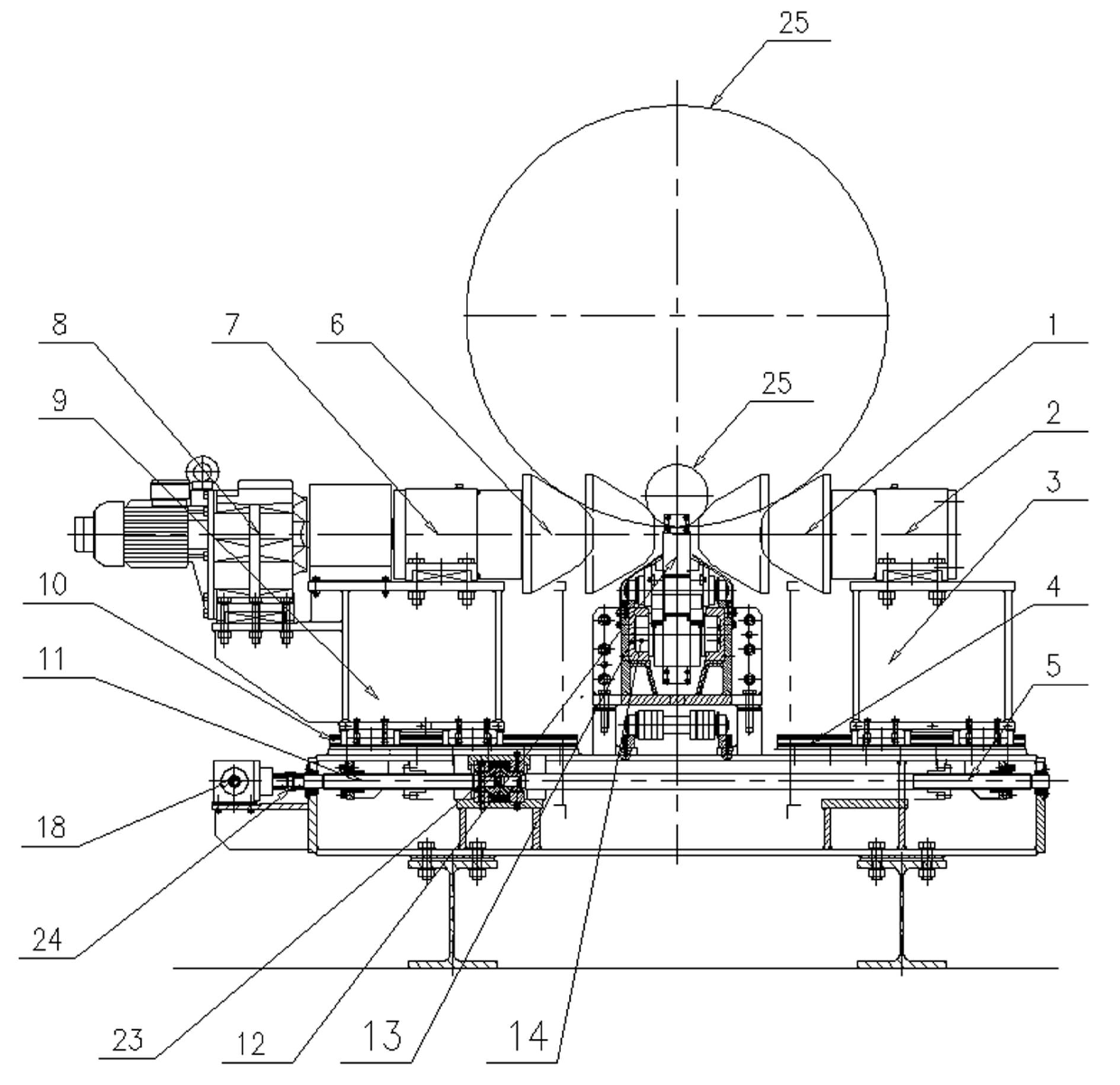
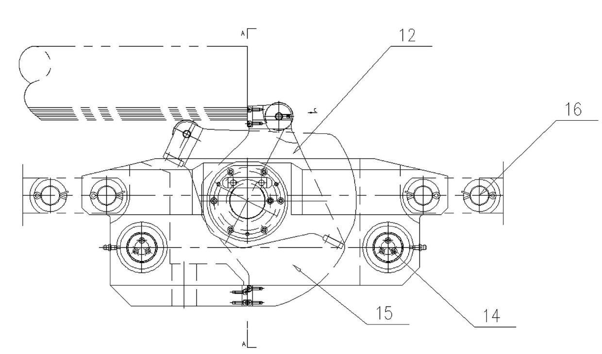
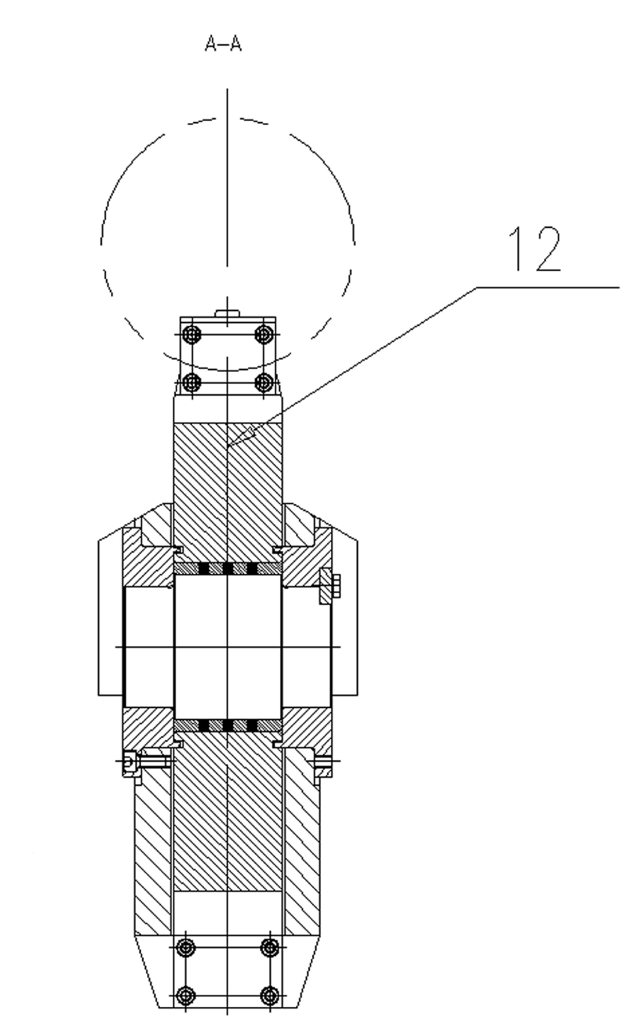
[0020] refer to Figure 1 to Figure 6 , a new positioning method for steel pipes when the steel pipes of the pre-welding machine are transported. When the steel pipes are sent to the steel pipe seaming machine, they are positioned at the same height as the lower bus bar of the steel pipes. The method is realized by the following embodiments.

[0021] A device for realizing a new positioning method for steel pipes when the steel pipes of the pre-welding machine are conveyed, including a steel pipe seaming machine, a steel pipe propulsion device arranged on the center line of the steel pipe seaming machine, and the left and right half conveying rollers of the steel pipes 25 of the pre-welding machine The road is arranged on the side of the center line of the steel pipe seaming machine, and the left and right half conveying rollers 6, ...


PUM


Abstract

The invention relates to a method for steel tube lower generatrix-based constant-height positioning during steel tube conveying of a tack welder and a realization device. The realization device comprises a steel tube seam closer, wherein a steel tube propulsion device is arranged at the center line of the steel tube seam closer, left and right half conveying roller ways of the steel tube are arranged at the lateral sides of the center line of the steel tube seam closer, left and right half conveying rollers are installed on bearing seats of the left and the right half conveying rollers, the bearing seats of the left and the right half conveying rollers are installed on left and right sliding tables, the left and the right sliding tables are installed on left and right sliding table guide rail pairs, the left and the right sliding table guide rail pairs are installed on a common base, left and right screwing lead screws for driving the sliding tables to move are connected together at the end heads by a connector, and the left and the right screwing lead screws are used for controlling the synchronous opening and closing of the left and the right half conveying rollers by a rotation control mechanism. By means of the positioning method and realization device provided by the invention, the damage to a tube propulsion device body due to the increase of tilting moment of a propulsor during large-caliber steel tube seam closing is avoided, the caliber minimization of the steel tube undergoing seam closing is simultaneously realized, and the minimal conveying caliber is reduced to Phi 210 from original Phi 508.

Description

technical field [0001] The invention relates to the technical field of pipe making, in particular to a new positioning method for steel pipes and a device for realizing them when the steel pipes are transported by a pre-welding machine. Background technique [0002] With the development of the oil pipeline industry and the promotion of the application of steel pipes in the construction industry, pipe making is booming in our country. The pipe industry has higher and higher requirements for pipe-making equipment, among which the wall thickness of the steel pipe is required to be larger and larger (up to 80mm), the specification range is wide (Ф324~Ф1626mm), and the material range is large (from structural steel to stainless steel) ). There are certain difficulties in the design of pipe-making equipment to meet these requirements. Some structures and methods cannot be realized according to the original concept. It is necessary to change the original thinking, adopt a new conc...

Claims


Application Information

Patent Timeline
Patent Type & Authority Applications(China)
IPC IPC(8): B23K37/00
Inventor 杨正法仝江涛杜海波吕毓军康文卓
Owner TIANSHUI METALFORMING MACHINE TOOL GROUP
Why Eureka
Try Eureka